1 ipmi firmware setup, 2 ipmi setup for the rack, Ipmi firmware setup – Kontron IPMI Firmware User Manual
Page 6: Ipmi setup for the rack
D R A F T — F O R I N
T E R N A L U S E O N L Y
6
www.kontron.com
User Guide
IPMI Fimware
To use the IPMI resources in a CompactPCI system requires an initial setup for IPMI operation. The fol-
lowing actions must first be performed to achieve operable IPMI functionality.
2.1.1 IPMI Firmware Setup
To select the BMC or the SMC mode, the
kIpmi uEFI Shell command is used. Upon every board reset, the
uEFI BIOS forwards the user settings (BMC or SMC mode) to the IPMI controller. The IPMI controller’s
factory default setting is SMC mode.
2.1.2 IPMI Setup for the Rack
For a working IPMI configuration, the SDRR of the BMC must be filled with all sensor data records of all
IPMI controllers in the rack. After every system start the BMC uses the SDRR to initialize all sensors of
all boards in the rack. The SDRR setup must be done by a management tool, e.g. the open-source tool
“ipmitool”, after system modification. Then the command is:
Table 1: BMC Mode vs. SMC mode
BMC MODE
SMC MODE
Fixed IPMB address: 20h
IPMB address is calculated based on the Geographical Adress
(GA), e.g. slot number: B0h (slot1), B2h (slot 2), ... BEh (slot 8)
System Event Log (SEL) storing all events sent to
BMC via IPMB
Events are sent to BMC (20h) via IPMB by default and are also
stored in the local System Event Log (SEL)
Sensor Data Record Repository (SDRR) may contain
all Sensor Data Records (SDR) of all IPMI control-
lers in the chassis
No SDRR
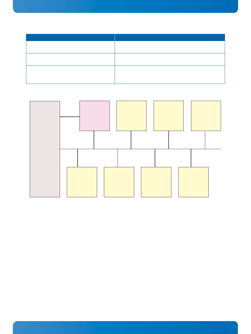
The IPMB address of the SMCs is determined by the geographic address of the slot.
IPMB-1
IPMB-0
IPMB-0
BMC
IPMB Address:
20h Fixed
SMC
IPMB Address:
B0h
SMC
IPMB Address:
B2h
SMC
IPMB Address:
B4h
SMC
IPMB Address:
B6h
SMC
IPMB Address:
B8h
SMC
IPMB Address:
BAh
SMC
IPMB Address:
BCh
Backplane