Introduction cp6004-ra/-rc – Kontron CP6004-RC User Manual
Page 36
Introduction
CP6004-RA/-RC
Page 1 - 16
ID 1055-1509, Rev. 1.0
D R A F T — F O R I N T E R N A L U S E O N L Y
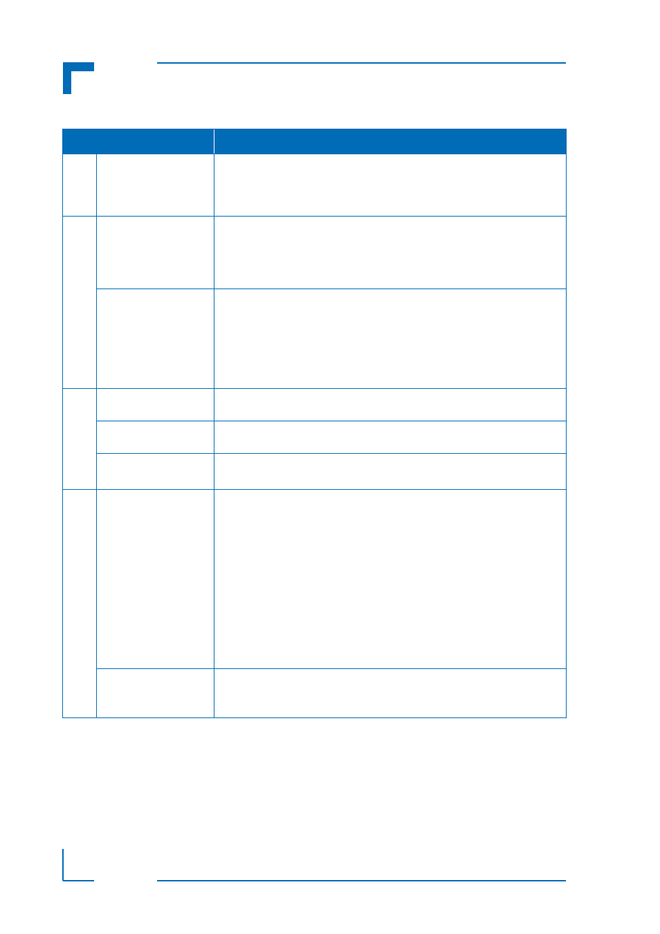
Interfaces
Serial ATA
One Serial ATA 6 Gb/s interfaces for:
•
One onboard SATA 6 Gb/s interface for the Serial ATA Flash module (up
to 64 GB flash memory)
Four SATA 3 Gb/s ports accessible via rear I/O
Sockets
Front Panel Connectors
(CP6004-RA)
•
DP: one 20-pin DisplayPort connector, J9
•
USB: two 4-pin,
type A connectors, J6 and J7
•
Ethernet: three 8-pin, RJ-45 connectors, J10, J11 and J12
•
Serial port: one 8-pin, RJ-45 connector, J8 (COMA)
•
PMC/XMC front panel bezel cutout
Onboard Connectors
•
PMC connectors J15 - J18 (Jn1 - Jn4)
•
XMC connector, J14
•
One 34-pin, SATA extension connector, J19
•
JTAG connector, J20
•
Debug connector, J22
•
XDP-SFF (debug) connector, J24
•
CompactPCI Connectors J1 - J5
Switches
DIP Switches
(CP6004-RA)
Three onboard DIP switches, SW1, SW2, and SW3, for board configuration
Reset Switch
(CP6004-RA)
One front panel hardware reset switch
Hot Swap Switch
(CP6004-RA)
One switch for hot swap purposes integrated in the front panel handle in
accordance with PICMG 2.1 Rev. 2.0.
LEDs
System LEDs
System Status LEDs on the CP6004-RA:
•
I0/I1 (red/green):
Indicate the software status of the IPMI controller
•
WD (green):
Watchdog Status
•
TH (red/green):
Temperature Status
•
HS (blue):
Hot Swap Control
System Status LEDs on the CP6004-RC:
•
I0/I1 (red/green):
Indicate the software status of the IPMI controller
(located on the rear side of the board)
Debug LEDs (CP6004-RA/-RC):
•
DLED0-3 (red/green): Onboard LEDs for debugging purposes
(located on the rear side of the board)
Ethernet LEDs
(CP6004-RA)
Gigabit Ethernet Status:
•
ACT (green):
Ethernet Link/Activity
•
SPEED (green/orange/off): Ethernet Speed
Table 1-2:
CP6004-RA/-RC Main Specifications (Continued)
FEATURES
SPECIFICATIONS