2 m12 100base-tx ports, Table 3-2 rj45 pin assignment – Kontron CP-RIO6-923-F User Manual
Page 24
Hardware Description
10
CP-RIO6-923-F User Guide
www.kontron.com
Note that ports marked with a „-“ are not available at the module.
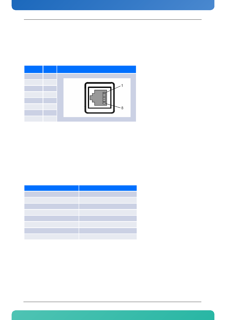
The RJ45 connectors are not equipped with LEDs for displaying the link status or activity. These are on the
switch board front panel.
The next table shows the pin assignment of one 10/100/1000BASE-T RJ45 connector.
3.2 M12 100BASE-TX Ports
The CP-RIO6-923-F-8M12 supports 100Base-TX operation on eight Industrial M12 D-coded female connec-
tors on the front panel. There is a separate magnetics device for each port.
The module supports PICMG 2.16 backplane ports FL12 to FL19. The switch interfaces which are accessible via
the CP-RIO6-923-F-8M12 are listed in the following table.
The RJ45 connectors are not equipped with LEDs for displaying the link status or activity. These are on the
switch board front panel.
Table 3-2:
RJ45 Pin Assignment
Signal
Pin
BI_DB+
1
BI_DB-
2
BI_DA+
3
BI_DD+
4
BI_DD-
5
BI_DA-
6
BI_DC+
7
BI_DC-
8
Table 3-3:
Ethernet Port Mapping
PICMG 2.16 Backplane Port
CP-RIO6-923-F-8M12 Port Label
FL_12
12x
FL_13
13x
FL_14
14x
FL_15
15x
FL_16
16x
FL_17
17x
FL_18
18x
FL_19
19x