Wiring, More information – KMC Controls VEP-43 Series User Manual
Page 2
VEB-46/VEP-43 Series 3-Way, NPT, Control Ball Valves (1⁄2 to 21⁄2")
2
Installation Guide
© 2013 KMC Controls, Inc.
050-019-51G
KMC Controls, Inc.
19476 Industrial Drive
New Paris, IN 46553
574.831.5250
www.kmccontrols.com
For additional instructions on wiring, feedback selec-
tor, and actuator/signal range reset (auto-mapping),
or
(fail-safe)
More Information
For non-fail-safe wiring,
auxiliary switches, feed-
back/direction selectors,
actuator/signal range reset
(auto-mapping), and other
For models, specifications,
and additional information,
on the
KMC web site.
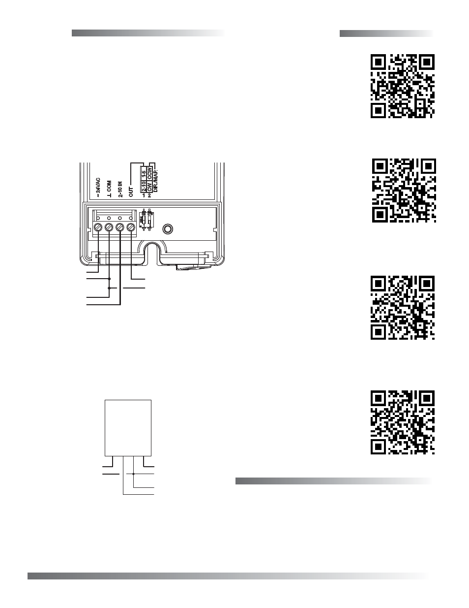
CL Wiring (MEP-4x52)
–
–
–
~/+
+
Control Signal
2–10 VDC
Power Supply
24 VAC/VDC
OUT (Green)
2–10 IN (White)
T
COM (Blac
k)
~24
V (Red)
+
Feedback Output
1–5 or 2–10 VDC
For information on assem-
bling a quick-mount “V”
actuator on a valve body, see
For fail-safe wiring,
auxiliary switches, feed-
back/direction selectors,
actuator/signal range
reset (auto-mapping), and
other information, see the
Wiring
NOTE: The installed actuator model is indicated
by the last two digits of the VEB valve
model number (e.g., VEB-46xxxxCK
has an MEP-4002V actuator) and the
last three digits of the older VEP valve
model number (e.g., VEP-43xxx745 has an
MEP-4002 actuator). For wiring and other
information about tri-state and other
actuators no longer sold mounted on
these valves, see the respective actuator’s
installation guide on the KMC web site.
CK/745 Wiring (MEP-4002)
NOTE: Before January 2014, MEP-40x2/48x2
models had 0–10 VDC inputs. They now
have 2–10 VDC inputs. When replacing an
older 0–10 VDC actuator with a 2–10 VDC
actuator, configure the connected controller
or thermostat output to match.
Power
Supply
~
–
–
+
Control Signal
2–10 VDC
–
+ Feedback Output
1–5 or 2–10 VDC