Wiring and dimensions, Maintenance, Important notices – KMC Controls CME-7002 User Manual
Page 2: Specifications
CME-7001/7002 Auxiliary Switches
2
Installation Guide
© 2009 KMC Controls, Inc.
826-019-02B
Important Notices
The material in this document is for information pur-
poses only. The contents and the product it describes
are subject to change without notice. KMC Controls,
Inc. makes no representations or warranties with respect
to this document. In no event shall KMC Controls, Inc.
be liable for any damages, direct or incidental, arising
out of or related to the use of this document.
Specifications
Switch Rating
12 A @ 250 VAC
1/3 HP @ 250 VAC
1/4 HP @ 125 VAC
Switch Point
Fully adjustable over 0 to 90°
actuator rotation
Connection
3 ft., 18 gauge cable
Material
Flame retardant plastic
Weight
CME-7001; 5.6 oz. (159 g)
CME-7002; 6.6 oz. (187 g)
Temperature Limits
Operating
–5 to 120° F (–21 to 49° C)
Shipping
–40 to 140° F (–40 to 60° C)
KMC Controls, Inc.
19476 Industrial Drive
New Paris, IN 46553
574.831.5250
www.kmccontrols.com
Maintenance
No routine maintenance is required. Each compo-
nent is designed for dependable, long-term reliabil-
ity, and performance. Careful installation will also
ensure long-term reliability and performance.
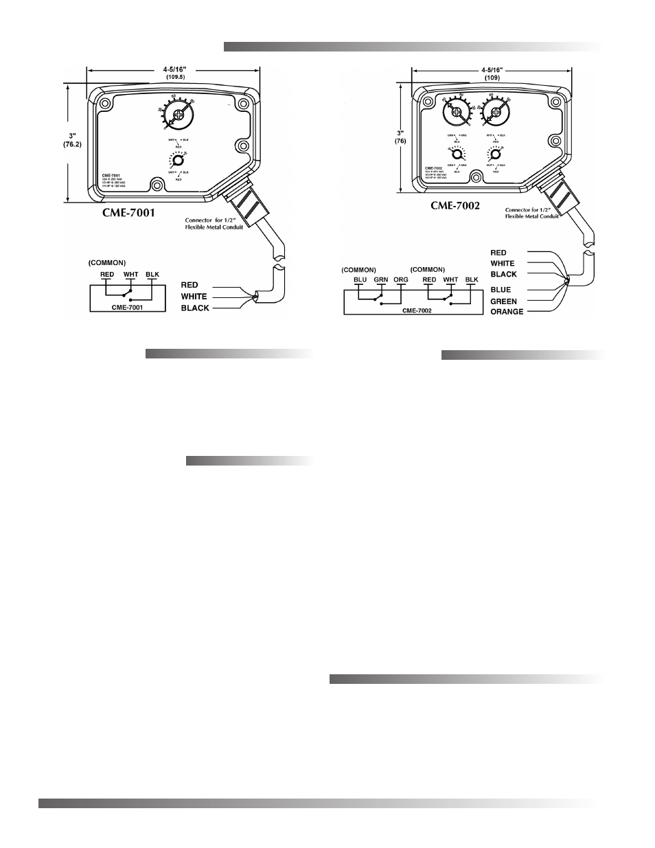
Wiring and Dimensions
Single SPDT Auxiliary Switch
Dual SPDT Auxiliary Switch