KMC Controls REE-5002 User Manual
Installation guide, Mounting, Connections and wiring
Installation Guide
Triac Relay Module, Fan with 2-Stage Reheat
REE-5002
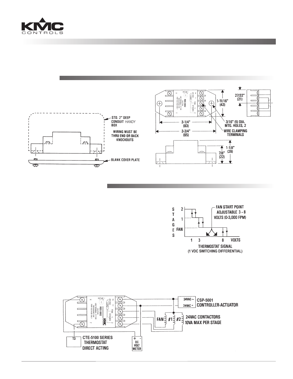
Mounting
Connect as shown below and/or in the sample
illustration on the next page. Supply the relay with
24 VAC, +20%/ –15%. (Use wire size of 14 to 22 AWG,
stranded.)
NOTE: Triac outputs
are for 24 VAC loads only.
Check the graph for thermostat signal setpoints and
corresponding stages. Stage 2 turns on at 1 VDC,
Stage 1 at 3 VDC, and the Fan at an adjustable level
beteen 3 and 8 VDC.
To adjust the Fan start point, connect a voltmeter
between the X and — terminals and then adjust the
potentiometer accordingly.
The
REE-5002 may be mounted directly to a control
box surface or in a 2 x 4" electrical handy box. Add a
blank cover to conceal the module if desired.
Connections and Wiring 1
Troubleshooting 2
Maintenance
REE-5002
Installation Guide
Connections and Wiring
NOTE: There is a 1 VDC switching differential on
each stage.