ISSPRO R82077 User Manual
Page 2
Form No. IS147 (Rev. A 03/11/2008
)
ISSPRO, INC.
2515 N.E. Riverside Way
Post Office Box 11177
Portland, Oregon 97211-1899
503-288-4488
800-888-8065
Fax: 503-249-2999
www.isspro.com
© 2008 ISSPRO, Inc. All Rights Reserved.
4
Find a location where fuel pressure can be measured such as a test port on the fuel pressure regulator.
This may require adapter fittings to accommodate the ⅛” NPTF sensor threads. For common rail
Cummins applications, ISSPRO offers a replacement Banjo bolt (R78822) with an ⅛” NPTF port.
DO NOT attempt to install in a location exposed to fuel rail pressure on common rail systems, as
these systems typically operate at over 20,000 PSI.
5
Install the new sensor. Pressure sensor threads are ⅛” NPTF.
Many Emission Control Devices are connected to temperature sensors or switches. Be careful not
to disable these when installing a sensor.
6
If leakage occurs at the sensor, tighten one-quarter turn at a time until leakage stops. If necessary,
thread sealant such as Teflon tape may be used.
When using a torque wrench, tighten approximately 20nm/15 lb-in. or slightly more, if leakage
occurs. Do not use the body of the sensor to tighten! Use only the hex and the correct wrench. Do
not over tighten!
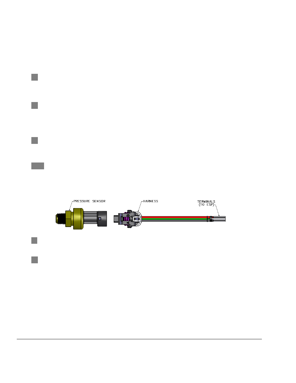
7
Connect the pressure sensor to the pressure sensor harness by pressing the connector into the
slot.
Figure 3: Pressure sensor and harness.
8
Connect pressure gauge to the ESP. (See ESP instructions for more details on how to do this).
Note: If drilling a mounting hole in a panel to mount this gauge, the hole size should be 2.040”.
9
Secure all wiring so that it does not interfere with moving parts or chafe on sharp edges. This may
be accomplished by routing the wiring within the factory wire harness sheath, using wire ties and
sheathing, and using appropriate grommets when passing through the firewall.