ISSPRO R82032 User Manual
Page 2
Form No. IS149 (Rev. A 03/11/2008
)
ISSPRO, INC.
2515 N.E. Riverside Way
Post Office Box 11177
Portland, Oregon 97211-1899
503-288-4488
800-888-8065
Fax: 503-249-2999
www.isspro.com
© 2008 ISSPRO, Inc. All Rights Reserved.
4
Install Pyrometer.
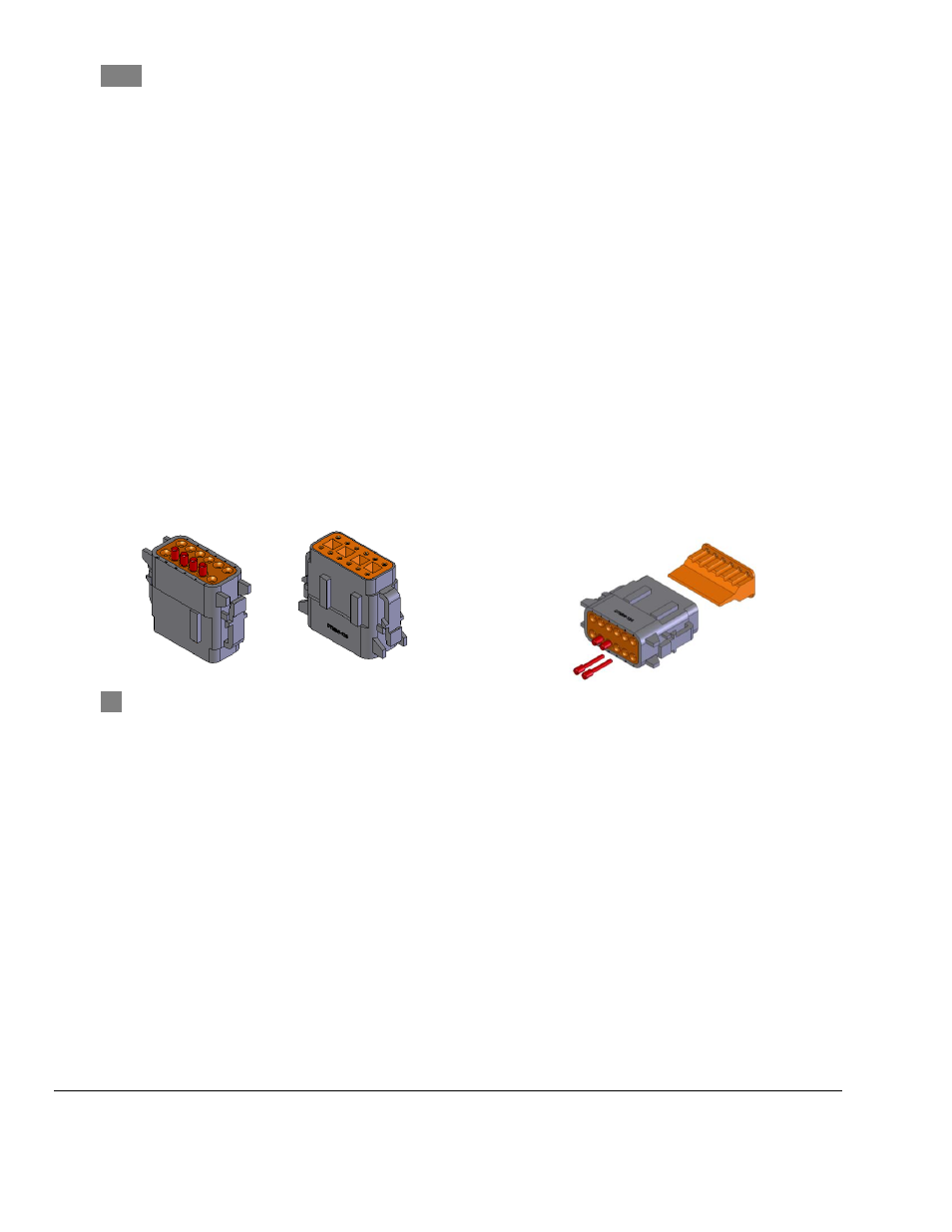
a. Remove plugs from cavities 8 and 9 of connector A (gray) of the ESP.
b. Using a pair of needle nose pliers, pull the orange wedge lock out of connector A.
c. Insert the terminal from the red wire (thermocouple (-)) into cavity 8 of connector A on the
ESP, pushing until it snaps into connector A.
d. Insert the terminal from the yellow wire (thermocouple (+)) into cavity 9 of connector A on
the ESP, pushing it until it snaps in place.
e. Note: Terminals will be close to flush with the top of the connector when fully seated.
f. A firm pull of the wire will confirm whether they are properly seated.
g. Push the orange wedge lock back into position. If any of the wires are not fully seated, the
wedge lock will not insert into position.
h. Reconnect connector A (gray) to the ESP.
i. Pyrometers require a 2.040” mounting hole; mount the pyrometer in the pillar or pod.
Connect the pyrometer to the ESP via the orange connector. See ESP Installation Instructions
for more details. The pyrometer has been set to ambient (room) temperature at the factory
and should not require further adjustment.
Figure 2: Connector A top and bottom
view. Shown with plugs and wedge lock
installed. Wires pre-installed in holes 1
through 7 and 12 are not shown.
Figure 3: Remove plugs and wedge lock as
shown. Wedge lock is replaced once wires are
positioned properly.
5
Secure all wiring so that it does not interfere with moving parts or chafe on sharp edges. This may
be accomplished by routing the wiring within the factory wire harness sheath, using wire ties and
sheathing, and using appropriate grommets when passing through the firewall.