ISSPRO R17032 User Manual
ISSPRO Measuring instruments
Form No. IS171 (Rev. F 02/07/2013
)
ISSPRO, INC.
•
2515 N.E. Riverside Way
•
Post Office Box 11177
•
Portland, Oregon 97211-1899
503-288-4488
•
800-888-8065
•
Fax: 503-249-2999
www.isspro.com
© 2008 ISSPRO, Inc. All Rights Reserved.
PYROMETER AND THERMOCOUPLE
INSTALLATION INSTRUCTIONS
I C O N K E Y
CAUTION
Tools may be required
Shown in picture
1
Disconnect batteries. Do not reconnect battery power until system
is fully configured to avoid risk of shock or fire.
2
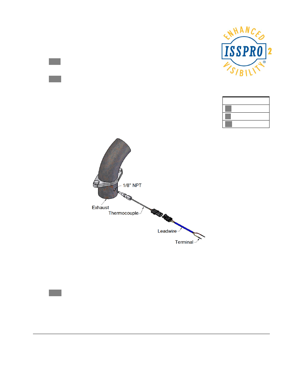
Install Thermocouple. The Thermocouple mounts into a ⅛” pipe
thread. If the exhaust manifold is already drilled and tapped, the
thermocouple can be installed at the location. If none is provided, drill (with
letter “R” bit) and tap the hole using ⅛” NPT tap. Apply a small amount of
anti seize lubricant to the exposed threads of the fitting and tighten using the
hex (wrench flats) which are closer to the tip of the thermocouple. Adjust
the depth of the probe (tip of the probe should be approximately at the
center of the exhaust flow), and tighten the outermost nut no more than one
full turn past finger tight.
3
Install Lead Wire. The lead wire assembly and the thermocouple are supplied with Delphi
connectors for assembly convenience. Simply snap together the connectors at either end of the
thermocouple and lead wire assemblies.
4
Trim the sensor harness wires to length, leaving enough length to allow the gauge to be pulled
from the pod or mounting location without disconnecting the connector. Carefully strip back the
sheathing from the outside of the sensor harness to expose 2” of the red, yellow and bare copper
wires. Do not strip the red or yellow wire insulation off.
Figure 1:
Exhaust, thermocouple and lead wire.