ISSPRO R17032 User Manual
Page 2
Form No. IS171 (Rev. F 02/07/2013
)
ISSPRO, INC.
•
2515 N.E. Riverside Way
•
Post Office Box 11177
•
Portland, Oregon 97211-1899
503-288-4488
•
800-888-8065
•
Fax: 503-249-2999
www.isspro.com
© 2008 ISSPRO, Inc. All Rights Reserved.
5
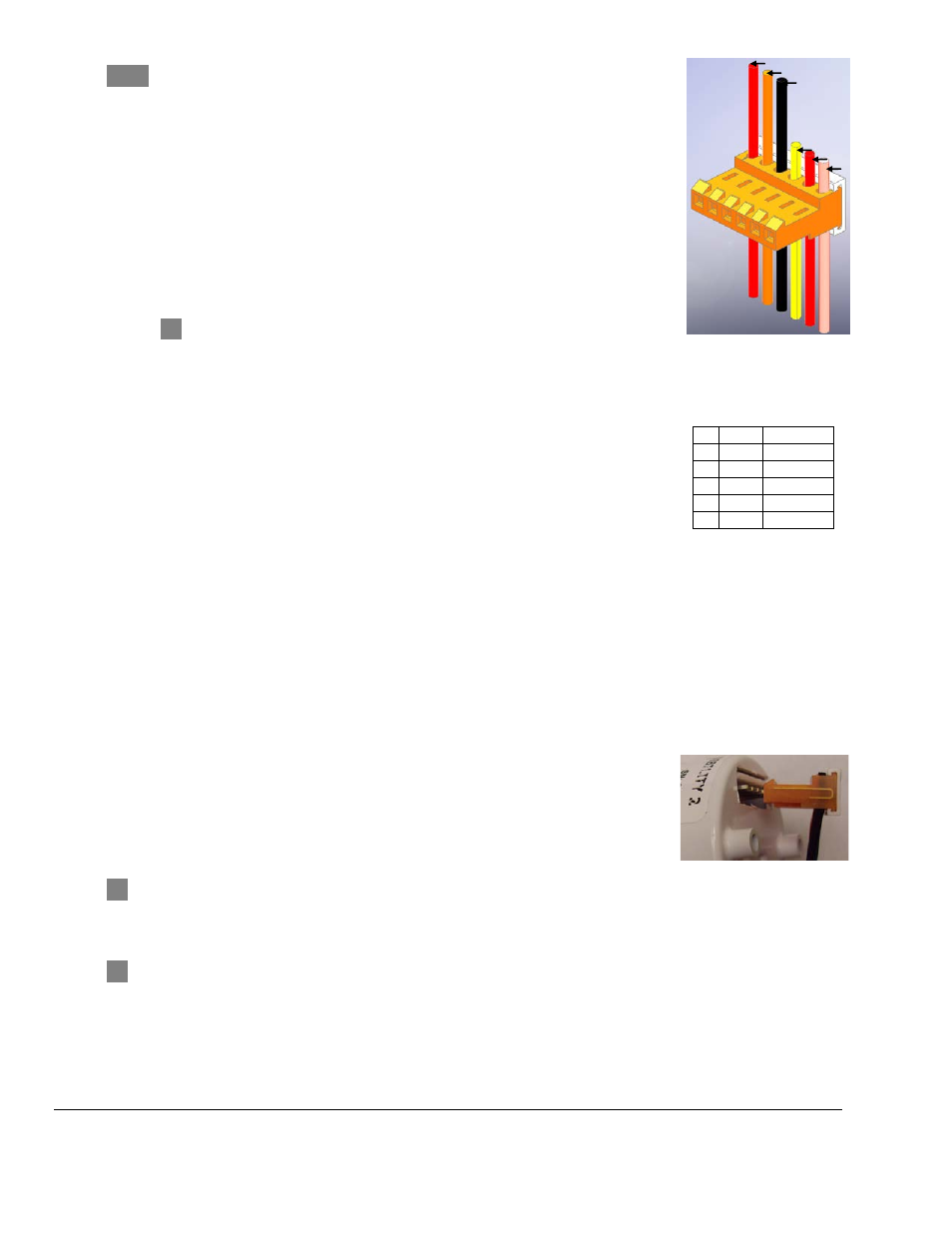
Install the three sensor harness wires along with the individual red,
orange and black wires into the orange insulation displacement connector
(see Fig.2 for positions), using the included wire insertion tool (R72023).
Follow the directions with the tool. DO NOT strip the wire ends, the
connector will pierce the wire insulation, and the insulation helps hold the
wire into the connector. Each wire must be pushed completely to the
bottom of its groove in the connector to ensure a good electrical
connection. Connect the other end of each of the remaining wires as
follows:
• Ignition – The red wire should be connected to a circuit that switches
on with the key switch.
Wire should be fused so as not to exceed 1 amp. If the
circuit does not have a fuse, or the existing fuse is higher than 1
amp, use an inline fuse.
• Dimmer – Connect the orange wire to the factory gauge dimmer
circuit by either tapping into the in-cab fuse block or by connecting
directly to the wire running from the dimmer on the headlight
switch.
• Ground – The black wire in pin #3 should connect to a clean ground
on the vehicle such as the battery negative terminal or a factory
ground bolt.
Figure 2: Connector.
1 Red
Ignition
2 Orange Dimmer
3 Black Ground
4 Yellow [+] Sensor
5 Red
[-] Sensor
6 Bare
Ground
Slide the white dust cover over the orange connector once the wires are securely installed.
NOTE: The gauge backlighting will only illuminate if both the ignition supply AND the backlighting
circuits are on.
OPTIONAL: Daisy Chain Your Gauges – If multiple EV
2
gauges are being installed in one location
(such as a pod), you may use a single set of the Ignition, Ground, and Dimmer wires to connect all of
the gauges. Simply pass the wires from one orange connector to the next one in a “daisy chain”
configuration.
6
Install the connector onto the back of the gauge (angled portion on end of
connector pointing up as shown in photo)
, and then secure the gauge in its
mounting location. If drilling a mounting hole in a panel to mount this
gauge, the hole size should be 2.040”. Mounting Kit R19999 is available for
larger mounting holes up to 2.200”.
NOTE!!! The orange connector MUST be installed in the direction shown. It is possible to
force it in backwards far enough to make an electrical connection, which will cause a short which may
damage the gauge, wiring, sensor, or your vehicle!
8
Secure all wiring so that it does not interfere with moving parts or chafe on sharp edges. This may
be accomplished by routing the wiring within the factory wire harness sheath, using wire ties and
sheathing, and using appropriate grommets when passing through the firewall.
Dimmer (orange)
Ground (black)
Ground (bare)
Ignition (red)
Sensor [+] (yellow)
Sensor [-] (red)