ETS-Lindgren HI-3637 VLF Magnetic Field Meter User Manual
Page 19
HI
n
3637 Manual
Page — 11
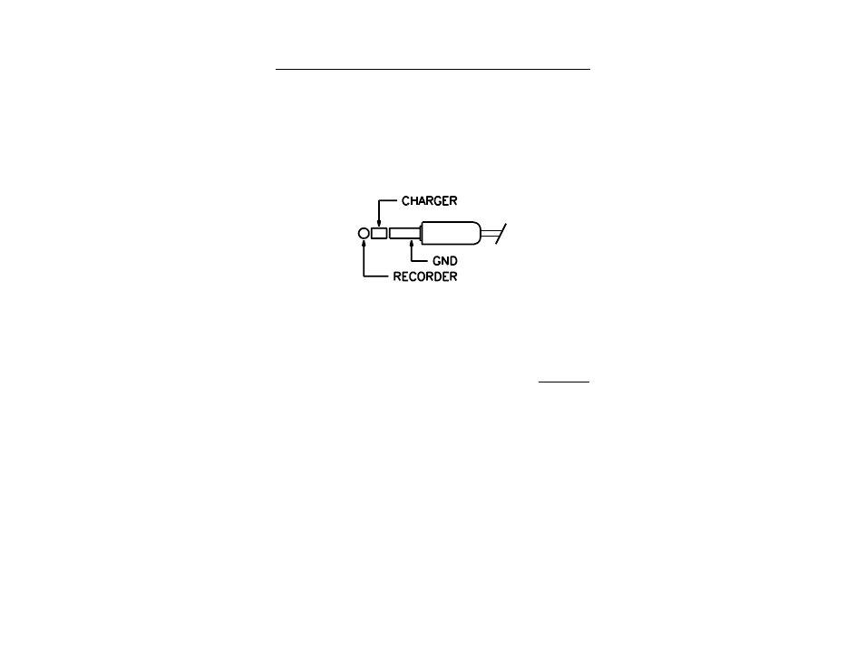
Figure 3
n
n
3
¼ inch Stereo Phone Plug
charger connector (refer to Figure 3
n
3). This is a two-
conductor jack that mates with a standard ¼ inch stereo
phone plug. The ring of the phone plug is reserved for
battery charger input and the tip is connected to the
recorder output. The shaft of the plug is common
ground. A diode in the charging circuit isolates the
battery voltage from the recorder output when the plug
is inserted into the jack.
The same circuit drives both the meter movement and the
recorder output. The maximum recorder output current
is 25 microamperes, requiring a 100 K
S
minimum
recorder output load; a lower impedance will affect the
accuracy of both the meter reading and the recorder
output voltage.
Both the meter movement and recorder output are driven
by a (PWM) pulse-width modulated signal from the
microprocessor. This leads to a small amount of ripple.
Low Battery Indication
The HI
n
3637 Magnetic Field Meter includes a "Low
Battery" indicator (LED) mounted on the front panel (refer
to Figure 3
n
2). It is normal for this LED to flash briefly
when switching ranges and when turning the instrument
off.
If the "Low Battery" indicator remains on during
operation, the battery must be recharged. When the
"Low Battery" LED lights, testing should be discontinued