Operation – ETS-Lindgren HI-2602 Interlock Monitor User Manual
Page 15
Operation
| 15
Operation
Before placing into operation, follow the safety
information in the ETS-Lindgren
Product Information Bulletin included with your
shipment.
The HI-2602 monitor and probe are calibrated as an integral unit. Care must be
taken not to interchange probes and monitors without recalibration. Operating the
HI-2602 with different probes may cause erroneous readings.
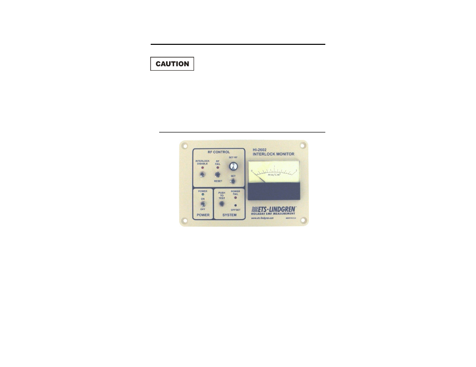
Front Panel Controls
RF Control—contains a switch for disabling the interlock and a red LED to
indicate when RF is over the preset RF fail level. A push button switch is used to
reset the system when the LED illuminates. A momentary toggle switch in
combination with a potentiometer is used to set the RF fail level.
Power—contains the main power switch and a green LED indicator for indicating
power on.
System—contains a potentiometer for adjusting the needle zero, a red LED
indicating power failure and a push button switch for testing the desired RF fail
level.
Analog Meter—indicates RF readings from 0 - 2 mW/cm².
- SMART 200 Reverb Chambers (45 pages)
- 6402 Helmholtz Coil (24 pages)
- 3625-2 LISN (15 pages)
- 3701 Line Probe (15 pages)
- 3725-2M LISN (19 pages)
- 3810-2 LISN (25 pages)
- 3816-2 LISN (21 pages)
- 3850-2 LISN (19 pages)
- 4825-2 LISN (25 pages)
- 1052 Antenna Tower Positioner (23 pages)
- 2005 Single Axis Positioner (32 pages)
- 2090 Controller (178 pages)
- 2110 Multi-Axis Positioning Systems (MAPS) (48 pages)
- 2115 Multi-Axis Positioning Systems (MAPS) (48 pages)
- 2165 Turntable (46 pages)
- 2171B Boresight Antenna Tower (64 pages)
- 2175 Antenna Tower (41 pages)
- 2181 Turntable (44 pages)
- 2187 Turntable (36 pages)
- 2188 Turntable (39 pages)
- 7-TR Tripod Positioner (49 pages)
- 7000-001 EMCenter Modular RF Platform (41 pages)
- 7405 E & H Near Field Probe Set (51 pages)
- 91197-1 Current Probe (57 pages)
- 95236-1 Current Probe (27 pages)
- HI-1501 Microwave Oven Survey Meter (28 pages)
- HI-1600 Microwave Oven Survey Meter (26 pages)
- HI-1710A Microwave Oven Survey Meter (57 pages)
- HI-1801 Microwave Oven Survey Meter (24 pages)
- HI-2200 RF Survey Meter (53 pages)
- HI-2790B Calibration Comparison System (44 pages)
- HI-3603 VLF Survey Meter (55 pages)
- HI-3604 ELF Survey Meter (44 pages)
- HI-3624(A) Survey Meter (22 pages)
- HI-3627 ELF Magnetic Field Meter (36 pages)
- HI-3637 VLF Magnetic Field Meter (48 pages)
- HI-3638 ELV/VLF Electric Field Meter (41 pages)
- HI-3702 Induced Current Meter (34 pages)
- HI-3804 RF Industrial Compliance Meter (25 pages)
- HI-4416 Numeric EMF Readout Unit (38 pages)
- HI-4433-CH Magnetic Field Probe (42 pages)
- HI-6005 Electric Field Probe (152 pages)
- HI-6100 Field Monitor (71 pages)
- HI-6113 Laser Data Interface and Probe Measurement System (49 pages)