Set-up and installation for all 1” valves, Set-up and installation for 11/2” valves, Ews, inc. / environmental water systems – Environmental Water Systems TT 1054 TWIN TANK User Manual
Page 4
EWS, Inc. / Environmental Water Systems
www.EWSWATER.com
4.3-4
PLUMB INLET
(supply)
AND OUTLET
(filtered)
INTO UNIT AND PLUMB BYPASS VALVE BETWEEN.
•
Follow the directional arrows molded onto the valve body. See picture below for correct set-up.
•
Use unions (a quick disconnect feature) at the inlet and outlet pipe, as pictured, to allow future servicing of
system without cutting and replumbing
•
Use Ball Valves (preferred - easy to turn on/off) at inlet/outlet pipes and bypass, as pictured for proper installa-
tion.
•
NO Heat, No Torch; Leave at least 12” between the valve body and any solder joints. Solder joints prior to
connecting to valve body. Failure to do this could cause interior damage. Teflon tape is the only sealant to used
on any of our fittings.
WARNING:
ONCE PLUMBED, DO NOT TURN ON WATER, UNTIL YOU BEGIN START-UP
PROCEDURES.
Inlet (supply) Side
Outlet (filtered)
Side
Bypass
Valve
Drain
Electric
11/2” 2850 Valve
Valve Cover: Black
NEMA 1 Rated
for resistence to
dust and moisture.
Hinged: left
Opens: from right
Controls: inside
DO NOT TURN ON WATER,
OPEN ANY VALVES OR
PLUG IN THE ELECTRICAL
UNTIL YOU GO TO THE
START-UP PROCEDURES
Back Side:
Front Side:
Drain:
1” MNPT
Connected (included) to:
Brass Flow Control
Housing with 10 GPM
Flow Restrictor
1” FNPT x 3/4” FNPT
Materials Needed for Drain:
3/4” copper x male adapter
3/4” union
3/4” (min) drain line
length to be determined
Materials Needed for Installation:
11/2” pipe length to be
determined
3 - 11/2” Ball Valves
2 - 11/2” Unions
See Drain Requirements
Union
Union
inlet
side:
supply
from
main
right
top view:
outlet
side:
to the
home
filtered
left
front:
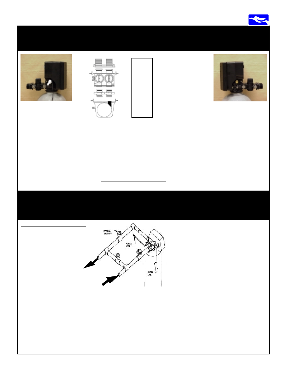
Inlet (supply) Side:
right side view of valve and
brine line with included
bypass and male yoke
USING THE CONNECTED BYPASS VALVE AND 1” MALE NPT YOKE.
PLUMB INLET (supply) AND OUTLET (filtered) INTO THE UNIT.
•
Follow the directional arrows molded onto the valve body and bypass. See pictures below for; top/front/back
and left/right views to prevent plumbing the unit backwards. Teflon tape is the only sealant to used on any of our
fittings. WARNING: No pipe dope.
•
NO Heat, No Torch; Leave at least 12” between the male yoke and any solder joints. Failure to do this could
cause interior damage. Consider flexible stainless (1”FNPT x 1”FNPT (3/4” if your application) and at least 18”
in length) connected to copper male adapters, or some other applicable connection - no heat, saves time, neat
install, if applicable/code to your application.
WARNING:
ONCE PLUMBED, DO NOT TURN ON WATER, UNTIL YOU BEGIN START-UP
PROCEDURES.
Outlet (filtered) Side:
left side view of valve and drain
port with included drain adaptor,
bypass and male yoke
Must use dual-port, full
flow, noryl bypass with
1” MNPT yoke.
•
Shuts off water to/from
the unit
•
No additional plumbing
for media replacement or
maintenance
•
Less costly plumbing
installation, easier start-
ups, non-corrosive
Yoke
1” MNPT
Dual
Port
Bypass
O-Ring
Connect
Valve
Head
back:
Set-Up and Installation for All 1” Valves:
RT 935, RT 1035, TT 1054
Set-Up and Installation for 11/2” Valves:
TT 1354-11/2