Dynojet 250: Replacing the Starter Ring Gear User Manual
Page 3
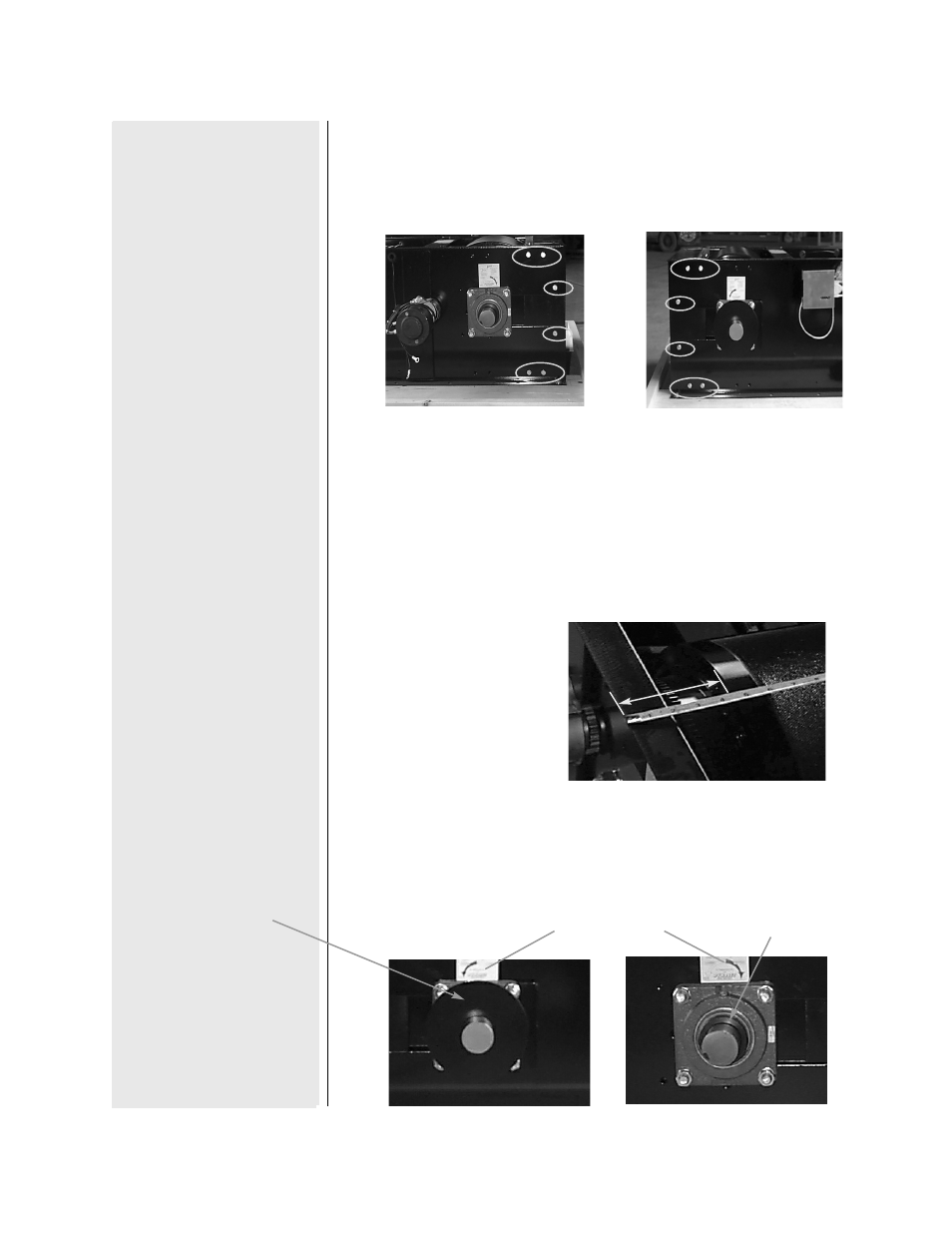
Step 2
Remove the (12), (8) if you had to perform step 1, 3/8” hex bolts on the
rear section of the frame. Remove the “C” channel section of the frame.
Step 3
Measure and take note of the drum orientation inside the frame. This
is crucial, as the dyno drum needs to be replaced in the exact same
location as it was before replacing the starter ring. Take measurements
from the face of the drum to the edge of the frame on both sides.
Step 4
Remove the bearing lock collars on both side of the drum. Loosen
the set screw and refer to the sticker on which way the collar
loosens. The right side lock collar is part of the pick up disk.
P/N 98221100
3
Take this Measurement on
both sides of the drum.
Lock collar is on the inside
of the pick up disk.
Lock collar
Lock Collar
Instructions