Led light head flash pattern – Code 3 WingMan for Crown Victoria User Manual
Page 8
8
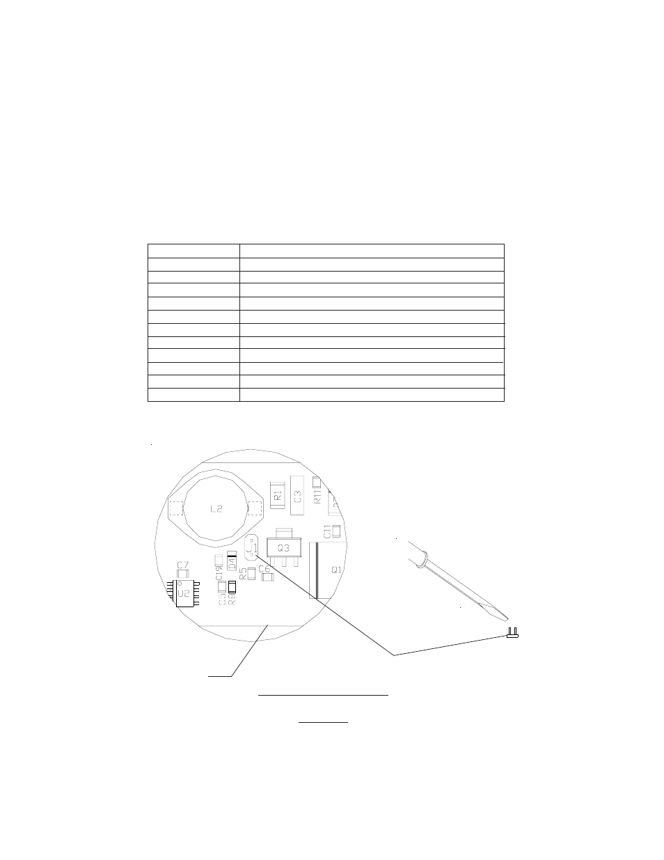
J1
Flash Pattern Header
FIGURE 6
PCB
LED Light Head Flash Pattern
Place the unit on a clean work surface and remove the outer cover. With the chassis facing up, locate
each lighthead
module circuit board.
To change the flash patterns of the LED Light Heads, touch both posts of
the J1 header
simultaneously with an electrically conductive tool such as a screw driver blade (see figure
6 below).
Repeating this proceedure allows the operator to cycle through the numerous flash patterns
offered until
the desired pattern is achieved.
Directional module Flash Pattern - Table 2
Flash Pattern
Description
Cycle Flash
Cycles through various patterns @ 70 fpm
Steady-Burn
Steady-Burn
Five Flash
Five Pulses per flash @ 70 fpm
Quad Flash
Four Pulses per flash @ 70 fpm
Triple Flash
Three Pulses per flash @ 70 fpm
Double Flash
Two Pulses per flash @ 70 fpm
Fast Double Flash
Two Pulses per flash @ 85 fpm
NFPA
Four Pulses, 70% Duty Cycle @ 75 fpm
Quad Pop Flash
Four Pulses per flash ( 3 equal, 1 extended) @ 70 fpm
Triple Pop Flash
Three Pulses per flash ( 2 equal, 1 extended) @ 70 fpm
Double Pop Flash
Two Pulses per flash ( 1 equal, 1 extended) @ 70 fpm