Operation, Surface mounting, Lamp mounting – Code 3 Volt User Manual
Page 2: Electrical connections, Figure 2, Figure 1
920-0211-00 Rev. A
Page 2 of 3
Operation:
After installing the system it is best to do a POWER-UP RESET the first time to ensure that all heads are in sync. Touch BLUE wires to +V (RED wire) while
applying power. Wait 1 second and then release the BLUE wires. All heads will reset to Pattern #2. (If you have installed a pattern select pushbutton, press
and hold pattern select while turning power switch ON.) To select a flash pattern, touch BLUE to +V or press pattern select switch to increment the flash
pattern. The heads will remember the flash pattern you have selected until it is changed again. When you increment past pattern #16 it will roll back around to
pattern #1.
Flash patterns 9 to 16 in the flash pattern list run through the patterns
listed in a continuous cycle.
If you are using this product to synchronize with an older product which only has flash patterns 1 through 8 then you may program this product to limit it’s flash
pattern list. Perform the following: Connect BLUE to RED (or press and hold pattern select button if installed. Connect to power and hold for 5 seconds. The
LED head will blink 1 time to indicate it is set for the old 8 pattern set, twice to indicate the 16 pattern set.
Surface Mounting:
Mark and drill mounting hole locations in mounting surface. Make the
electrical connections described below and feed the driver module through
the mounting hole. Silicone RTV sealant should be used around the
mounting and screw holes. Install the bezel using the two screws provided.
SURFACE MOUNTING
DO NOT USE LED HEAD
WITHOUT DRIVER MODULE!
0.575”
[14.61]
1.65”
[41.91]
DRIVER MODULE
MOUNTING SURFACE
0.688”
[17.46]
1.8”
[45.72]
0.094”
[2.38]
2.27”
[57.66]
BEZEL
SCREWS
MOUNTING HOLE
BEZEL OUTLINE
3/32” DRILL
FIGURE 2
LAMP MOUNTING
DO NOT USE LED HEAD
WITHOUT DRIVER MODULE!
3.12”
[79.25]
0.345”
[8.75]
1.505”
[38.23]
0.175”
[4.45]
0.695”
[17.65]
DRIVER MODULE
1.0”
[25.40]
1.28”
[32.51]
0.094”
[2.38]
SCREWS
GASKET
MOUNTING
SURFACE
MOUNTING HOLE
3/32” DRILL
The LED heatsink will get hot during
operation but will NOT melt any of the
plastic parts of the lens assembly.
DO NOT TOUCH the heatsink
during operation.
FIGURE 1
Lamp Mounting:
Pick a location in the vehicle lamp housing that is at least 1” away from any
existing bulbs. Drill 1” hole in vehicle lamp reflector housing with hole saw.
Mark the two screw hole locations and drill with 3/32” bit. Install the LED
head into lamp housing with gasket as shown in Figure 1. Use silicone RTV
on the screws to seal the threads.Strap the driver module to a nearby wire
harness or body structure. Make electrical connections as described below.
Electrical Connections:
RED: Connect to +V through an ON/OFF switch. The use of a fuse located close to the voltage source is recommended. Size the fuse according to the
number of heads used in the system. 18AWG or larger wire is recommended.
BLACK: Connect to - GROUND vehicle chassis. 18AWG or larger wire is recommended.
BLUE: Flash pattern SYNC and SELECTION wire. If you wish to have all the LED heads synchronize their flash timings and patterns with each other then all
the BLUE wires must be connected together. (64 Heads Maximum) The BLUE wire is also used to select the flash pattern. Touch the BLUE wire to +V to
select the next pattern in the FLASH PATTERN LIST. The BLUE wire can also be run to a momentary push-button located on the dashboard to allow the
flash pattern to be changed when desired. Note: Do not connect the BLUE wire to - Ground. It will disrupt the flash pattern sync signal.
YELLOW: Alternating / Simultaneous selection. Connect to either +V or GROUND (GND).
The YELLOW wire makes the head fire AT THE SAME TIME or ALTERNATING with the other heads in the system.
Heads with YELLOW connected to +V fire at the same time. Heads with YELLOW connected to GND fire at the same time.
Heads with YELLOW connected to +V will ALTERNATE with heads that have YELLOW connected to GND.
The YELLOW wire has no function in STEADY ON mode.
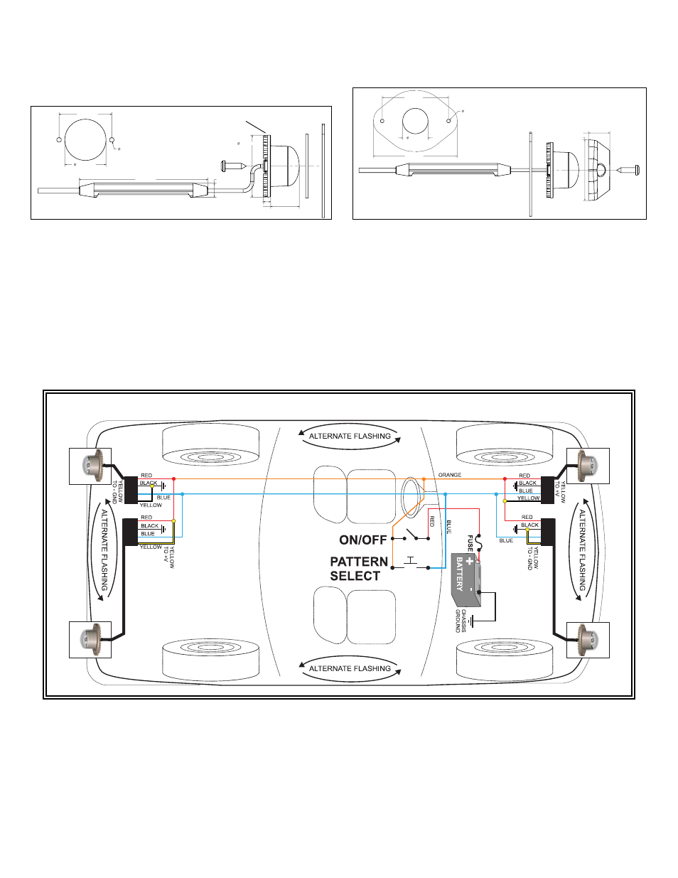
INSTALLATION OF 4 HIDE-A-LED™ USING PATTERN SELECT SWITCH PANEL (OPTIONAL) ON DASHBOARD.