Installation and mounting instructions – Code 3 SuperVisor_3Up_OPTIX_2011_Ford_F150 User Manual
Page 3
3
Installation and Mounting Instructions
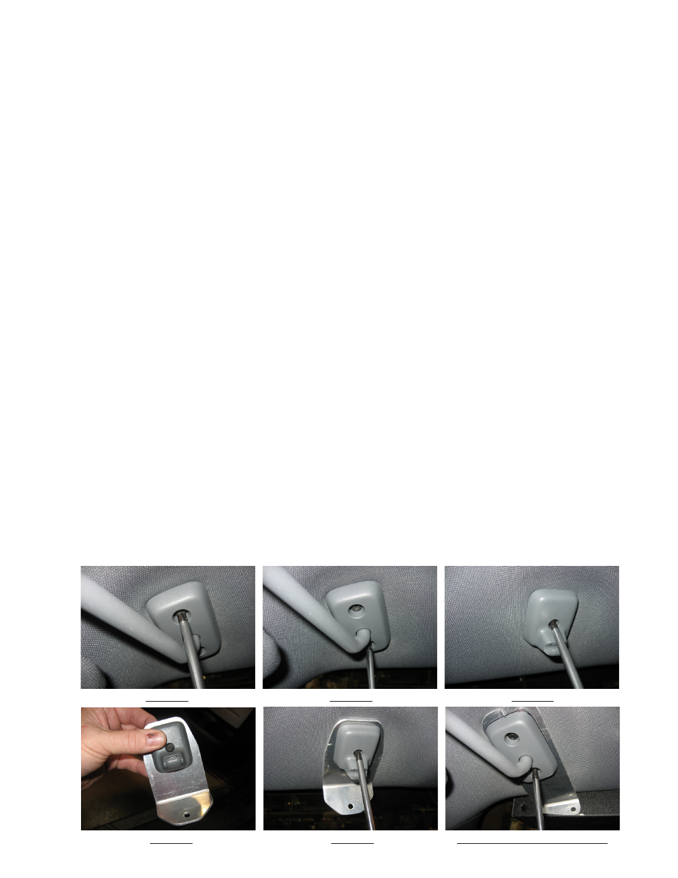
FIgURE
1
FIgURE
2
FIgURE
3
FIgURE
4
FIgURE
5
FIgURE
6-DRIVER SIDE SHOwN
Step 1
Remove the (2) small Phillips screws as shown in Figures 1 and 2 from each pivot bracket. Pull the visor pivot brackets down
from the headliner and carefully allow the sun visors to hang by the vehicle's attached vanity mirror light wires if so equiped.
Step 2
Unscrew the single Phillips screw holding each of the vehicle's (2) inner visor clips in place as shown in Figure 3.
Step 3
Attach the vehicle's inner visor clips to the SuperVisor Inner Mounting Brackets as shown in Figure 4. Thread each of the vehi-
cles Phillips screws you removed in step 2 above all the way up into the vehicle's plastic inner visor clip (this makes it easier to see the
end of the screw so you can thread the screw into it's hole in the headliner). Position the SuperVisor Inner Mounting Brackets up to
the headliner as shown in figure 5 and loosely thread the screws into the screw hole in the vehicle's headliner. Tighten the screws until
the brackets are within about 1/8" of the headliner. Allow the brackets to remain loose and do not fully tighten the screws at this time.
Step 4
Attach the vehicle's plastic outer visor pivot brackets to the supplied SuperVisor Outer Mounting Brackets and thread the (2)
supplied #8 X 1" Black Phillips Truss Head Sheet Metal Screws as shown in Figure 6 (Drivers Side Shown). Note: Be very careful to
tuck the vanity mirror light wires, if so equiped up in the hole in the headliner and out of the way to avoid pinching the wires.
Tighten the mounting screws until the brackets are within about 1/8" of the headliner. Allow the brackets to remain loose and do not fully
tighten the screws at this time.
Step 5
Route the SuperVisor's cable to the desired side of the vehicle and out the end of the SuperVisor's Outer Panel. Make sure
the cable will not interfere with the vehicle's headliner and windshield as you position the SuperVisor up to the headliner in front of the
SuperVisor Inner and Outer Mounting Brackets as shown in Figure 7 page 4.
Step 6
Line up the slots in the SuperVisor Inner Mounting Brackets with the threaded holes in the SuperVisor, and thread the supplied
1/4"-20 screws and internal tooth lock washers through the slots and into the SuperVisor's Outer Panel (see Figure 8 page 4).
Step 7
Line up the slots in the SuperVisor's Outer Mounting Brackets with the threaded holes in the SuperVisor, and Thread the sup-
plied 1/4"-20 screws and internal tooth lock washers through the slot in the SuperVisor's Outer Mounting Brackets and into the SuperVi-
sor's Outer Panel (see Figure 9 page 4).
Step 8
Make sure the SuperVisor is exactly centered in the vehicle and tighten all (4) of the #8 X 1" Black Phillips Truss Head Sheet
Metal Screws in the Outer Mounting Brackets and the vehicle's (2) small Phillips screws in the Inner Mounting Brackets (See Figure 10
page 4 for the Outer Mounting Brackets see Figure 11 page 4 for the Inner Mounting Brackets).
Step 9
While pushing the SuperVisor very tightly up against the headliner, tighten the (2) 1/4"-20 SuperVisor Inner Mounting Bracket
screws as shown in Figure 12 then again while pushing the SuperVisor very tightly up against the headliner, tighten the (2) 1/4"-20
SuperVisor Outer Mounting Bracket screws as shown in Figure 13 page 4. Note: It is best to have an assistant push up on the
SuperVisor while you tighten the screws to assure that the SuperVisor is tight against the vehicle's headliner.