Step 5 mounting the supervisor tl, Step 3 attach the pivot arm brackets – Code 3 SuperVisorTL for 2007 Chevy Tahoe User Manual
Page 4
Step 5 Mounting the SuperVisor TL™
Once all four sun visor brackets are attached, the SuperVisor TL is ready to be installed. Tilt the rear view mirror down as far out of the
way as possible (see Figure 16). Carefully move the SuperVisor TL into position above the rear view mirror by tilting one end up as
shown in Figure 17 with the front outer tip of the SuperVisor TL located slightly in front of the corner post of the vehicle, then swing the
other end up into position being very careful not to scratch the plastic corner post covers.
Line up the mounting holes in the outer mounting brackets with the threaded holes in the SuperVisor TL and thread the supplied 1/4"-
20 bolts and internal tooth lock washers into the SuperVisor TL's Outer Panel (see Figure 18). Line up the mounting holes in the inner
mounting brackets with the threaded holes in the SuperVisor TL and loosley thread the supplied 1/4"-20 bolts and internal tooth lock
washers into the holes in the SuperVisor TL's Outer Panel as shown in Figure 19. Carefully tighten the three torx screws in each of the
two outer pivot brackets by tightening each screw a little at a time (see Figure 12). Note: Tightening the three screws each a little at
a time helps prevent cracking the OEM plastic pivot bracket. Tighten the two torx screws in the center inner mounting brackets (see
Figure 15). Tighten the two 1/4-20 bolts in the Outer Mounting Brackets (see Figure 20). While pushing up firmly on the SuperVisor TL's
Outer Panel to close up the gaps as much as possible between the SuperVisor TL's outer panel and the vehicle's headliner fabric,
tighten the two 1/4-20 bolts at the inner mounting brackets (see Figure 21). Replace the plastic visor pivot bracket covers and snap the
small inner visor clip covers closed.
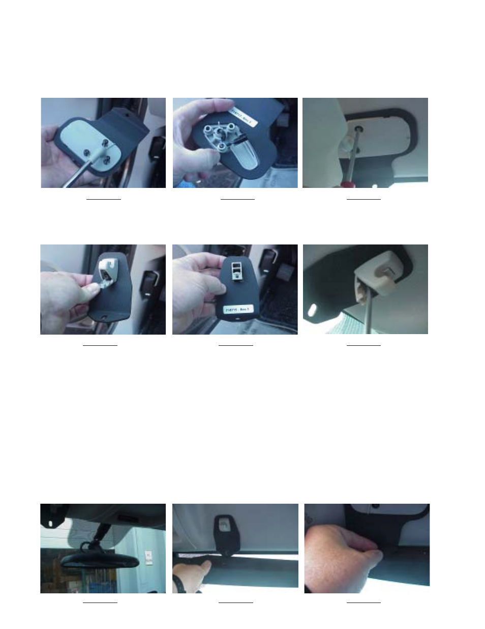
Step 4 Attach brackets to sun visor retaining clips
Place the inner bracket on the retaining clip as shown in Figures 13 and 14. Attach the inner bracket and retaining clip to the headliner
with the torx screw as illustrated in Figure 15. Leave the torx screws slightly loose at this time.
Step 3 Attach the pivot arm brackets
Attach the outer mounting brackets that are supplied noting the difference between passenger and driver side brackets (see Figure 10
Note:The Driver side is shown). Rotate the pivot arm on the Driver's side sun visor and verify the orientation of the outer bracket as
shown in Figure 11. Replug the wire terminal that goes to the visor mirror vanity light, if the vehicle is so equiped, and carefully tuck the
wire and terminal back into the elongated slot in the headliner as you position the Driver's side pivot arm. Attach the three torx screws as
shown in Figure 12. Repeat this operation for the Passenger side pivot arm and outer mounting bracket. Leave the torx screws slightly
loose at this time.
FIGURE
10
FIGURE
11
FIGURE
12
FIGURE
13
FIGURE
14
FIGURE
15
FIGURE
16
FIGURE
17
FIGURE
18
4