Warning – Code 3 PSE LED F12 12 Output Flashers User Manual
Page 5
5
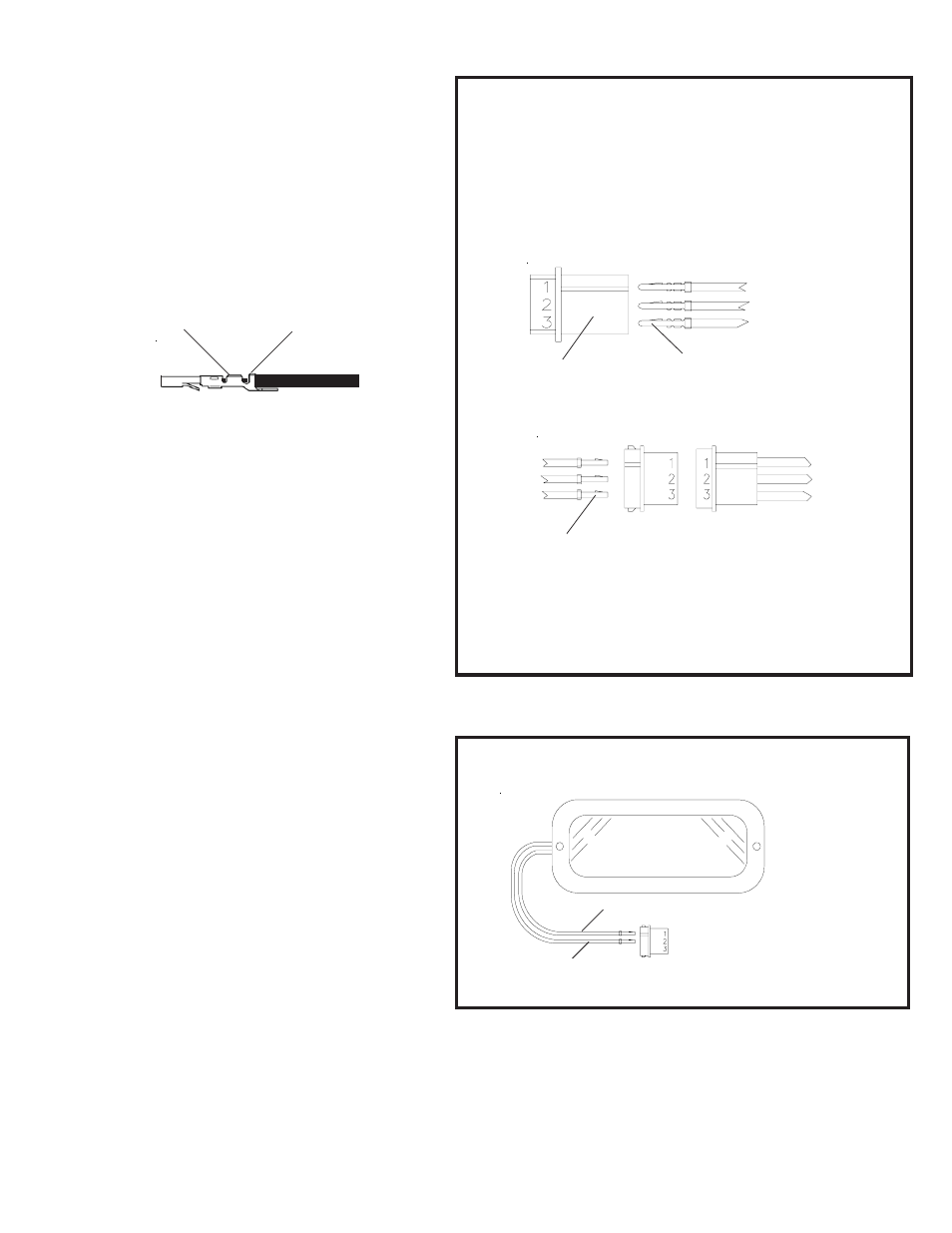
EXTENSION CABLE WIRING
MALE AMP CONNECTOR
(to terminate the LED-EX
Lighthead harness)
Insert wires with male pins into
the proper locations in the male
AMP connector:
POWER WIRE - HOLE #1
GROUND WIRE - HOLE#2
CONTROL WIRE - NOT USED
(if applicable)
AMP-p/n 1-480305-0
POWER WIRE - HOLE #1
GROUND WIRE - HOLE#2
CONTROL WIRE - HOLE #3(not connected)
Insert wires with female pins into
the proper locations in the female
AMP connector:
AMP-p/n 61118-4
AMP-p/n 61117-4
FEMALE AMP CONNECTOR
from LED
Lighthead
Extension
Cable
AMP-p/n 1-480303-0
Remote LED Lightheads (2 wire installation)
Code 3
LED-EX
Lighthead
RED
BLACK
POWER WIRE - POSITION 1
GROUND WIRE - POSITION 2
Self Contained LED-EX Lighthead in Steady-Burn Mode
Figure8
Extension
Cable
Figure7
WARNING!
CODE 3 LED-EX Lighthead Termination Instructions:
a) Strip coating back from wire 1/8".
b) Crimp wire into terminal at position 'A' and
crimp wire coating at position 'B' of AMP
socket P/N 61117-4.
c) Pull on wire to ensure a quality crimp
(soldering is recommended to ensure good
connection).
d) Insert pins into AMP connector # 1-480303-0
as shown in figure 8.
IMPORTANT
For continued reliability, RTV or waterproofing grease
must be used on all terminals to prevent corrosion and
premature failure of the connections.
Install the LED light heads in the preferred locations.
String the 3 conductor cable between each individual
light and the Flasher. Make sure the cable is secure
along the chosen routing inside the vehicle to prevent
it from damage by chafing or binding. Be sure to keep
the cable away from engine hot spots.
Insert the AMP Mate & Lock pin contacts P/N 61118-4
on each end of the extension cables into the AMP
connectors P/N 1-480305-0. Each end of these cables
has a factory crimped terminal on each of the three
wires, see Figure 7.
Note: It is important to follow the correct color code
when inserting the pins into the AMP
connectors.
1. Plug the extension cables to the LED light
heads.
2. Plug the other end of the cable into the light
head output socket on the flasher, see Figure 1.
A
B