Flash - pattern programming, Figure5, Figure6 – Code 3 PSE LED F12 12 Output Flashers User Manual
Page 4
4
Flash - Pattern Programming
A. Lightbar Version:
The desired flash pattern for any of the progressive operation modes 1, 2, & 3 can be programmed as follows:
1. Power one Mode-control wire at a time. Example: If the Mode1 flash pattern is to be programmed,
connect +12V to only the Mode1 control wire.
2. Connect the yellow (PGM) wire momentarily to +12V and release it to select the next available
pattern. Repeat until the desired pattern is selected. (refer to page 1 for available flash patterns)
3. Repeat steps 1 & 2 above for all three Mode-control wires one at a time. Note: Mode 3 overrides
Mode 2 and Mode 2 overrides Mode 1.
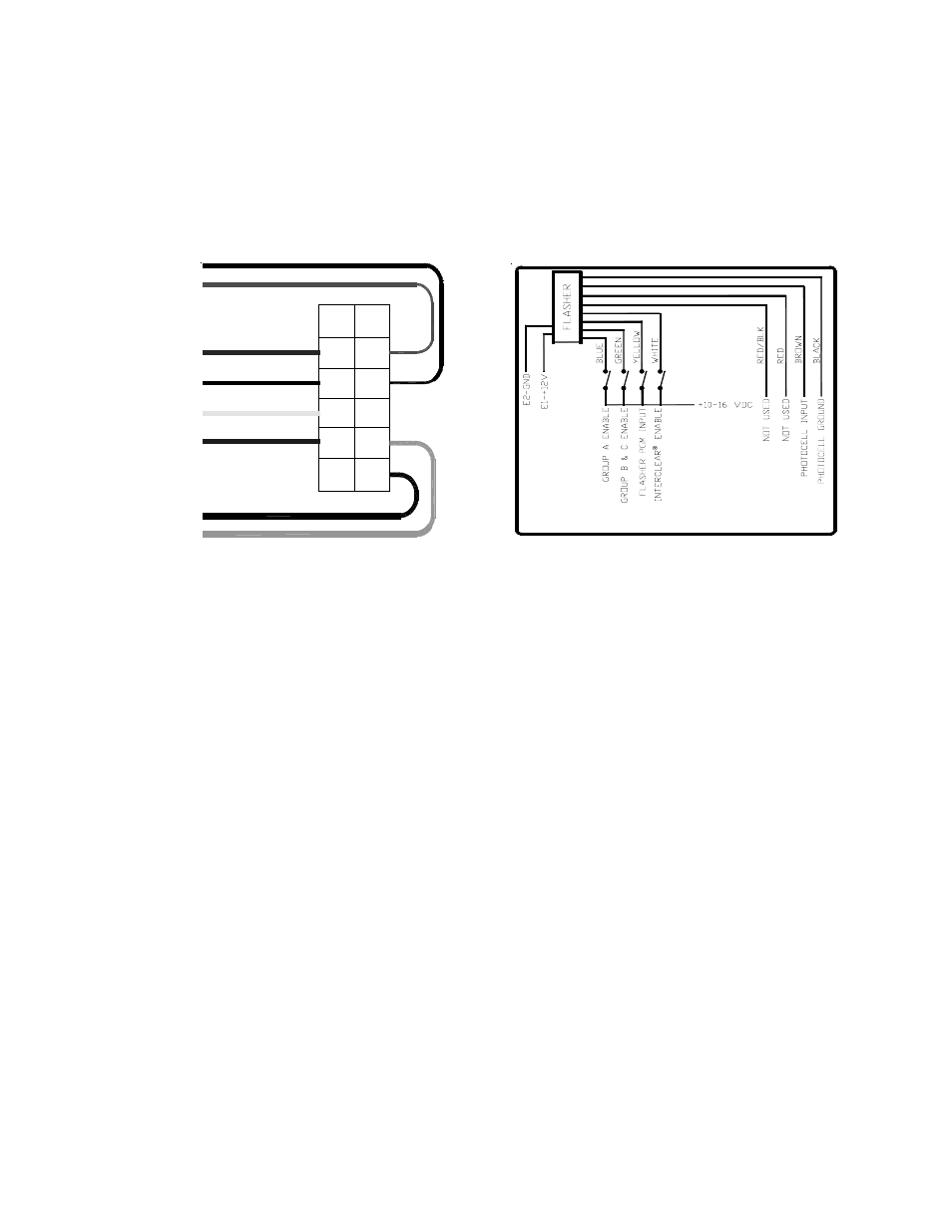
B. Remote Version:
1. Enable the blue and/or green wires first to select regular operation pattern.
2. Apply 10-16 VDC momentarily to the yellow wire, repeat until desired pattern is selected.
3. Repeat steps 1 & 2 enabling the white wire in addition to the blue and/or the green wire to select
the desired Interclear® mode flash pattern.
4. Tape or ground the yellow wire when programming is complete. Note: Interclear® Mode
overrides regular operation mode.
Figure5
18 AWG RED/BLACK
WIRE DESIGNATION:
18 AWG BROWN
18 AWG RED
18 AWG WHITE
18 AWG YELLOW
18 AWG GREEN
18 AWG BLUE
2. Blue:
10-16V Group A Enable
3. Yellow:
10-16V Flash Pattern PGM (Momentary)
4. White:
10-16V Interclear® Enable
5. Brown:
Photocell Input
7. Black:
Photocell Ground
8. Green:
10-16V Group B & C Enable
10.Red/Blk:
Not Used
11.Red:
Not Used
1
2
3
4
5
6
7
8
9
10
11
12
18 AWG BLACK
Figure6
Remote Version Wiring Diagram