Figure4, Figure3 – Code 3 PSE LED F12 12 Output Flashers User Manual
Page 3
3
2. Remote LED Flasher version p/n T08097:
This version has the same connector interface as the Low Profile version, except that this version utilizes
direct circuit board headers rather than wire harnesses. This Flasher can be used as a remote LED flasher to
drive Code 3 LED-EX and LED Perimeter lights. It can also be used as a motorcycle LED flasher.
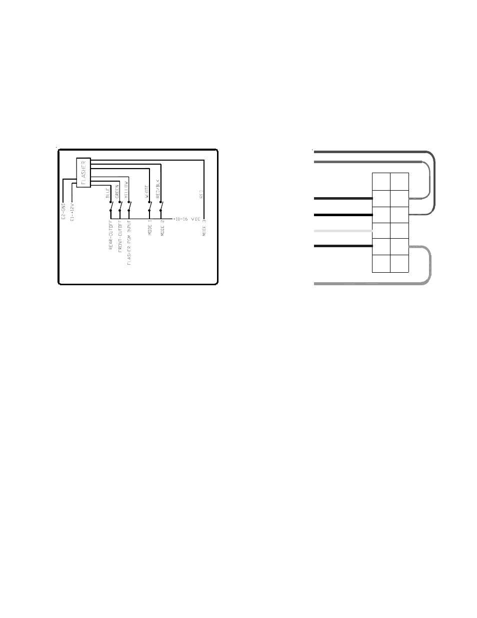
Figure4
18 AWG RED/BLACK
CONTROL HARNESS WIRE DESIGNATION:
18 AWG BROWN
18 AWG RED
18 AWG WHITE
18 AWG YELLOW
18 AWG GREEN
18 AWG BLUE
1
2
3
4
5
6
7
8
9
10
11
12
2. Blue:
10-16V Rear Cutoff
3. Yellow:
10-16V Flash Pattern PGM
4. White:
10-16V Mode1
5. Brown:
Not Used
8. Green:
10-16V Front Cutoff
10.Red/Blk:
10-16V Mode2
11.Red:
10-16V Mode3
12.Black:
Not Used
INSTALLATION & WIRING
1. First, install the Flasher in a protected location using the flasher itself as a template. Make sure all connectors
are easily accessible. (Refer to Figure 5 and 6 for the following steps).
2. Plug in the Control Harness provided with the Flasher p/n T08115.
3. Connect the +12V and ground wires to quickslide terminals E1 & E2 respctively. Ensure that the +12V power
wire is fused with a 15 Amp Auto style fuse. Note: Use 14 Ga. wire for the main +12V and ground
connections.
4. Optional: Connect the yellow wire (flash pattern) program wire to +12V through a momentary switch. This
switch can be used to program a different flash pattern for regular and Interclear® operation. This wire can also
be taped away or permanently grounded after the flasher has been programmed with the desired patterns.
5. Optional: Connect the white (Interclear® Enable) wire to the active high interclear output on the siren if
applicable.
6. Connect the green (Group B & C Enable) wire and the blue (Group A Enable) wire to +12V through two use
supplied SPST switches. These switches could be used to activate groups A, B and C respectively.
7. Connect the brown (Photocell Input) and the black (Photocell Ground) wires to the red and black wires of the
photocell cable p/n T08086 if photocell activated Group C output dropout operation is desired. Otherwise, tie
these two wires together to disable this option.
Figure3
Lightbar Version Wiring Diagram