Warning – Code 3 OsciLaser Flushmount User Manual
Page 3
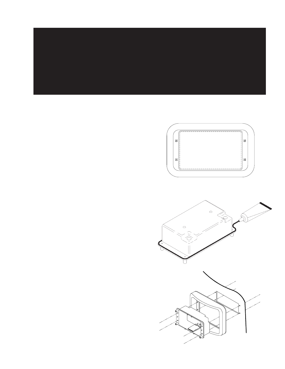
FIGURE 1
FIGURE 2
NOTE: All of the information listed in this booklet must be
given to the end user by the installer.
1) Using the trim bezel as a template, inscribe the position
for mounting the OsciLaser
TM
as shown in Figure 1. To
access and mark mounting holes, the gasket must be
pierced with an ice pick or a sharp pointed object. Be
sure to mark positions for the four mounting holes when
completing this task.
2) At these inscribed positions, first drill the holes for the
mounting screws using 3/16" drill bit. If it is not possible
to access the product from behind the surface being
mounted, a 1/8" drill bit should be used for the sheet
metal screws also included in the mounting kit. Once
this is accomplished, cut the rectangular hole for the
housing.
3) Using
GE Silicone II or a sealant with equal properties,
lay a small bead around the housing as shown in Figure
2. This bead must be placed on the outer edge of the
housing to ensure a proper and effective seal.
4) Slide the housing into the trim bezel and through to the
hole on the vehicle as illustrated in Figure 3. Make sure
the housing is oriented properly with the drain hole on the
bottom and the two wiring holes at the top.
5) Once the housing and bezel are positioned in the hole,
use the four #8 x 1-1/2" stainless steel machine screws,
nuts, washers and lockwashers to secure the assembly
to the vehicle (Figure 4). At this point, make sure that any
excess sealant is wiped clean from the assembly. As
noted in step 2, if accesss to the back of the mounting
surface is not possible, it will then be necessary to use
the four #8 x 1-1/4" stainless steel, sheet metal screws
provided. In this situation, steps 6 through 8 must be
competed before the bezel/housing assembly is affixed
to the vehicle.
FIGURE 3
Particular attention should be paid to the location and method of making electrical
connections and splices to protect these points from corrosion and loss of conductivity.
Ground terminations should only be made to substantial chassis components, preferably
directly to the vehicle battery. The user should install a fuse sized to approximately 125% of the
maximum Amp capacity in the supply line to protect against short circuits. For example, a 30
Amp fuse should carry a maximum of 24 Amps. DO NOT USE 1/4" DIAMETER GLASS
FUSES AS THEY ARE NOT SUITABLE FOR CONTINUOUS DUTY IN SIZES ABOVE 15
AMPS. Circuit breakers are very sensitive to high temperatures and will "false trip" when
mounted in hot environments or operated close to their capacity.
WARNING!
3