Step 3 - attach the pivot arm brackets, Step 5 mounting the supervisor mc – Code 3 MC SuperVisor Tahoe User Manual
Page 4
4
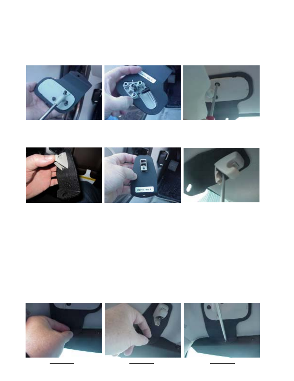
Step 3 - Attach the pivot arm brackets
Attach the outer mounting brackets that are supplied noting the difference between passenger and driver side brackets (see
Figure 10) Note: The Driver side is shown (The bracket you have may differ slightly from what is shown). Rotate the
pivot arm on the Driver's side sun visor and verify the orientation of the outer bracket as shown in Figure 11. Re-plug the
wire terminal that goes to the visor mirror vanity light, if the vehicle is so equipped, and carefully tuck the wire and terminal
back into the elongated slot in the headliner as you position the driver's side pivot arm. Note: Take extra care that neither
the wires nor the connector get pinched. Attach the three Torx screws as shown in Figure 12. Repeat this operation for
the Passenger side pivot arm and outer mounting bracket. Leave the Torx screws slightly loose at this time.
Step 4 Attach brackets to sun visor retaining clips
Place the inner bracket on the retaining clip as shown in Figures 13 and 14. Attach the inner bracket and retaining clip to the
headliner with the Torx screw as illustrated in Figure 15. Leave the Torx screws slightly loose at this time.
Step 5 Mounting the SuperVisor MC™
Route the cable either behind the plastic A pillar cover or through the small cut out in the Unit's Outer Panel. Carefully
raise one half of the Unit into position behind the mounting brackets. Line up the slotted mounting holes in the inner and
outer mounting brackets with the threaded holes in the Unit while holding it up as level as possible against the windshield.
Thread the supplied 1/4"- 20 bolts & internal tooth lock washers into the Unit's Outer Panel (see Figures 16 & 17). Tighten
the screws to just finger tight. Repeat this step for the other half of the Unit. Tighten the three Torx screws in each of the two
outer pivot brackets by tightening each screw a little at a time (see Figure 12 above). Note: Tightening the three screws
each a little at a time helps prevent cracking the OEM plastic pivot bracket. Tighten the two Torx screws in the center
inner mounting brackets (see Figure 15 above). While pushing up firmly on the Unit's Outer Panel at each mounting point to
close up the gaps as much as possible between the Unit's outer panel & the vehicle's headliner, tighten each of the 1/4-20
bolts in the mounting brackets (see Figure 18 & 19 page 5). Note: In some cases you will need to simultaneously pull
down on the mounting brackets so that when you release the unit it stays up tight enough to ensure light from the
light heads does not get through! Replace the plastic visor pivot bracket covers (see Figure 20 page 5) & snap the small
inner visor clip covers closed. Each half of the Unit will look as shown in Figure 21 on page 5.
FIGURE 10 FIGURE 11 FIGURE 12
FIGURE 13 FIGURE 14 FIGURE 15
FIGURE 16 FIGURE 17 FIGURE 18