Installation instructions cont, Warning, Wiring instructions – Code 3 MC SuperVisor Caprice User Manual
Page 6: Led fusing considerations
6
FIgURE
25-DRIVER SIDE
FIgURE
26-PASSENgER SIDE
Installation Instructions Cont.
Caution: Drilling into the housing of the light bar could damage wiring or other internal
components.
Larger wires and tight connections will provide longer service life for components. For high current wires it
is highly recommended that terminal blocks or soldered connections be used with shrink tubing to protect
the connections. Do not use insulation displacement connectors (e.g. 3M
®
Scotchlock type connectors).
Route wiring using grommets and sealant when passing through compartment walls. Minimize the
number of splices to reduce voltage drop. High ambient temperatures (e.g. under hood) will significantly
reduce the current carrying capacity of wires, fuses, and circuit breakers. Use "SXL" type wire in engine
compartment. All wiring should conform to the minimum wire size and other recommendations of the
manufacturer and be protected from moving parts and hot surfaces. Looms, grommets, cable ties, and
similar installation hardware should be used to anchor and protect all wiring. Fuses or circuit breakers
should be located as close to the power takeoff points as possible and properly sized to protect the wiring
and devices. Particular attention should be paid to the location and method of making electrical connections
and splices to protect these points from corrosion and loss of conductivity. Ground terminations should
only be made to substantial chassis components, preferably directly to the vehicle battery. The user should
install a fuse sized to approximately 125% of the maximum Amp capacity in the supply line to protect
against short circuits. For example, a 30 Amp fuse should carry a maximum of 24 Amps. DO NOT USE
1/4" DIAMETER GLASS FUSES AS THEY ARE NOT SUITABLE FOR CONTINUOUS DUTY IN SIZES
ABOVE 15 AMPS. Circuit breakers are very sensitive to high temperatures and will "false trip" when
mounted in hot environments or operated close to their capacity.
WARNINg!
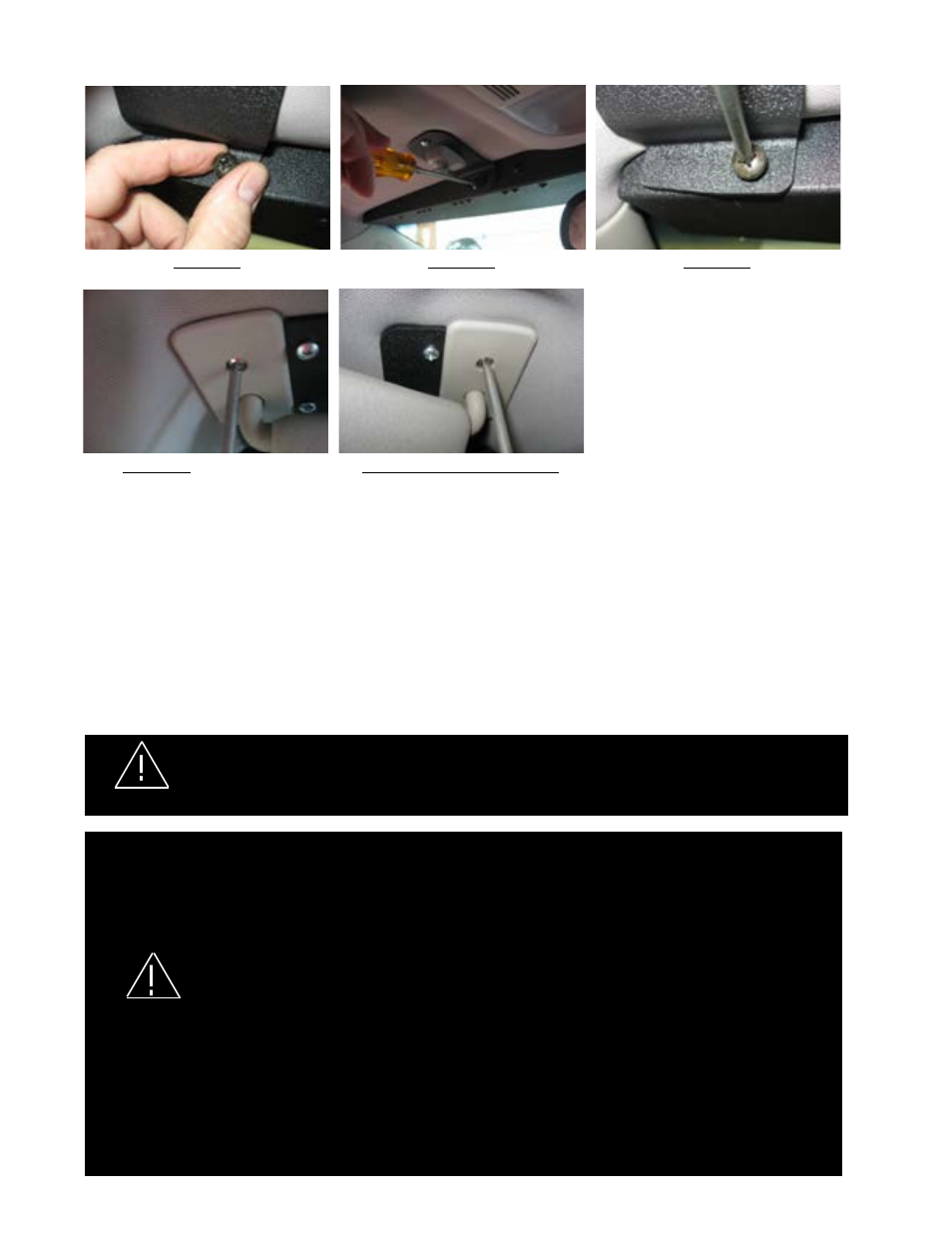
FIgURE
22
FIgURE
23
FIgURE
24
Wiring Instructions
Finish routing the cable as desired. It is advisable to leave an extra loop of cable when installing the light bar to allow for
future changes or reinstallations. For wiring of the Multi Color SuperVisor, see pages 7 & 8.
LED Fusing Considerations
NOTE:
The Components of the Multi Color SuperVisor System are circuit protected by the Multi Color SuperVisor System CC
Board so the individual wires in the System do not require fusing.
DO NOT APPLY 12 VOLTS DIRECTLY TO THE SUPERVISOR WIRES AFTER IT IS CONNECTED TO THE
SUPERVISOR MULTI COLOR CC BOX. THE MULTI COLOR SUPERVISOR CC BOARD OR THE LIGHT
HEADS COULD BE DAMAGED BY APPLYING 12 VOLTS TO THE CC OUTPUTS!.
WARNINg!