Installation & mounting, Warning – Code 3 LED DuoBeam User Manual
Page 3
3
Utilizing non-factory supplied screws and/or mounting brackets and/or the
improper number of screws may result in loss of warranty coverage on the
equipment.
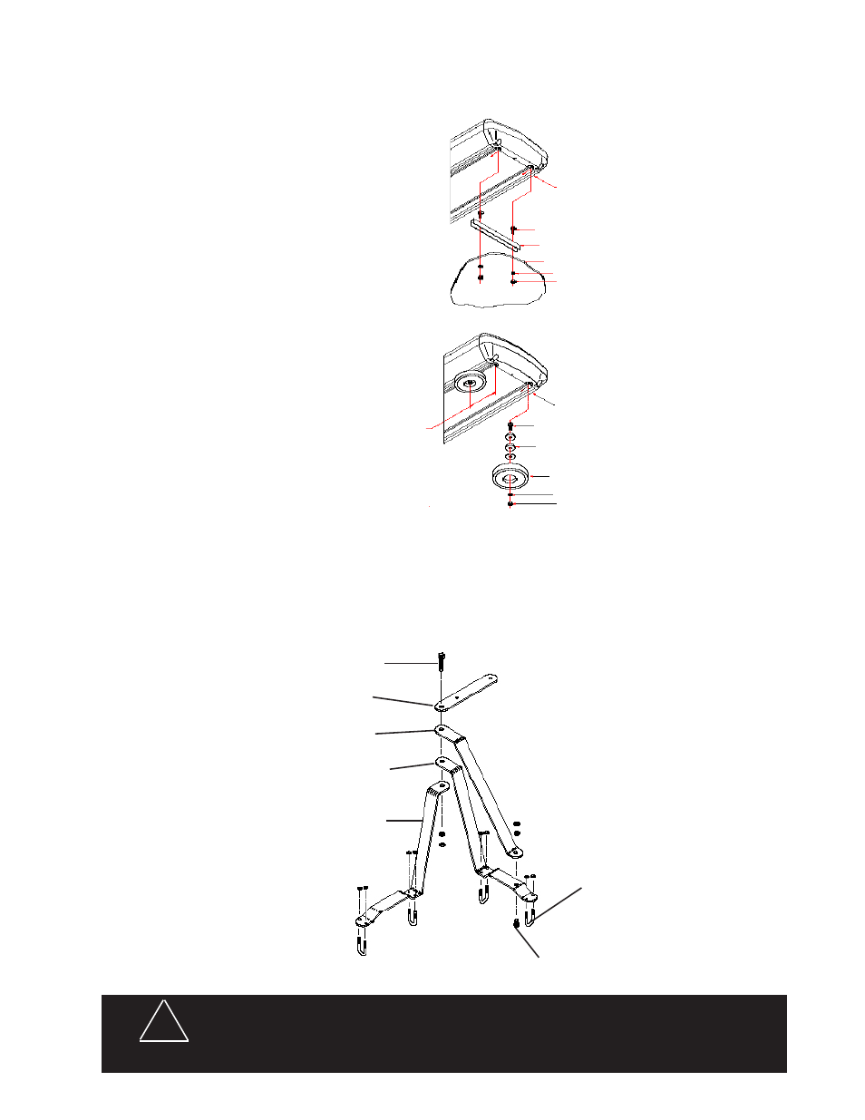
FLUSH MOUNT
Slide bolts through track in
bottom of beacon. Place spacer
over bolts as shown in FIGURE 1.
Align bolts with pre drilled holes in
vehicle's surface. Place lock washer
and nut on bolt then tighten until snug.
BOTTOM END VIEW OF BEACON
5/16-18 X 1 1/2" CARRIAGE BOLT (PN 240)
NOTE: Spacer must be used to prevent water from entering the bar.
fIguRE 1
MOLDED SHIM (PN 1064)
RB 80 MAGNETIC BASE (PN 499)
5/16" SPLIT WASHER (PN 245)
5/16-18 SS HEX NUT (PN 244)
MAGNETIC MOUNT
Slide bolts through track in bottom of ..
beacon approximately 2.25 inches from
end. Place molded shims over bolts as
shown. Attach magnetic base over bolts.
Place lock washer and nut on bolt then
tighten until snug.
MOUNTING SPACER (S50179)
5/16-18 SS HEX NUT (PN 244)
5/16" SPLIT LOCK WASHER (PN 245)
VEHICLE MOUNTING SURFACE
Installation & Mounting
5/16-18 X 1 1/2" CARRIAGE BOLT (PN 240)
7/16 BOLT
DuO BEAM MOuNTINg
BRACKET
BRACE
BRACKET B
BRACKET A
u-BOLT
3/8 BOLT
MIRROR MOUNT BRACKET
1. Assemble the brackets, tighten the 3/8 bolt but leave the 7/16 bolt finger tight at this time.
2. Position bracket assembly on top mirror supports, bracket A on rear support and bracket B on front sup-
port. Note: some mirror designs require reversing bracket A and B. Rotate bracket A as necessary to get
the best fit. Some additional bending of brackets may be necessary in some cases to achieve a satisfac-
tory fit.
3. Attach bracket assembly to mirror supports with U-bolts, position bracket assembly as desired and tighten
U-bolts. The Duo Beam mounting bracket should be parallel to the ground.
In all cases, mount the lightbar so that the rubber edging that fits between the lens and the alu-
minum base faces to the front or the side of the vehicle.
WARNINg!
!