Torus, Integrated flasher in lighthead), Prizm ii – Code 3 DuoBeam II User Manual
Page 6: And tricore, Modules with central controller, Flash pattern description
6
Torus
TM
(Integrated flasher in lighthead)
Flash Pattern Description
1. Cycle Flash (DEFAULT)--------------Cycles through various patterns @ 70 fpm
2. NFPA Quad Flash 80 FPM-----------Four Pulses per flash @ 80 fpm
3. Quad Flash 70 FPM--------------------Four Pulses per flash @ 70 fpm
4. Steadyburn-------------------------------Steady-Burn
5. Five Flash 70 FPM---------------------Five Pulses per flash @ 70 fpm
6. Triple Flash 70 FPM ------------------
Three Pulses per flash @ 70 fpm
7. Double Flash 70 FPM-----------------Two Pulses per flash @ 70 fpm
8. Single Flash 70 FPM------------------One Pulse per flash @ 70 fpm
9. Quad Pop Flash 70 FPM-------------Four Pulses per flash ( 3 equal, 1 extended) @ 70 fpm
10. Triple Pop Flash 70 FPM------------
Three Pulses per flash ( 2 equal, 1 extended) @ 70 fpm
11. Mod Flash
12. Cycle Flash 150 FPM-----------------Cycles through various patterns @ 150 fpm
13. Five Flash 150 FPM-------------------Five Pulses per flash @ 150 fpm
14. Quad Flash 150 FPM------------------Four Pulses per flash @ 150 fpm
15. Triple Flash 150 FPM -----------------
Three Pulses per flash @ 150 fpm
16. Double Flash 150 FPM---------------Two Pulses per flash @ 150 fpm
17. Single Flash 150 FPM----------------One Pulse per flash @ 150 fpm
18. Single Flash 250 FPM----------------One Pulse per flash @ 250 fpm
19. Single Flash 375 FPM------------------One Pulse per flash @ 375 fpm
0
0
1
1
2
9
9
9
9
2
1
LOC
LOC
LOC
9
9
9
9
1
2
1
2
3
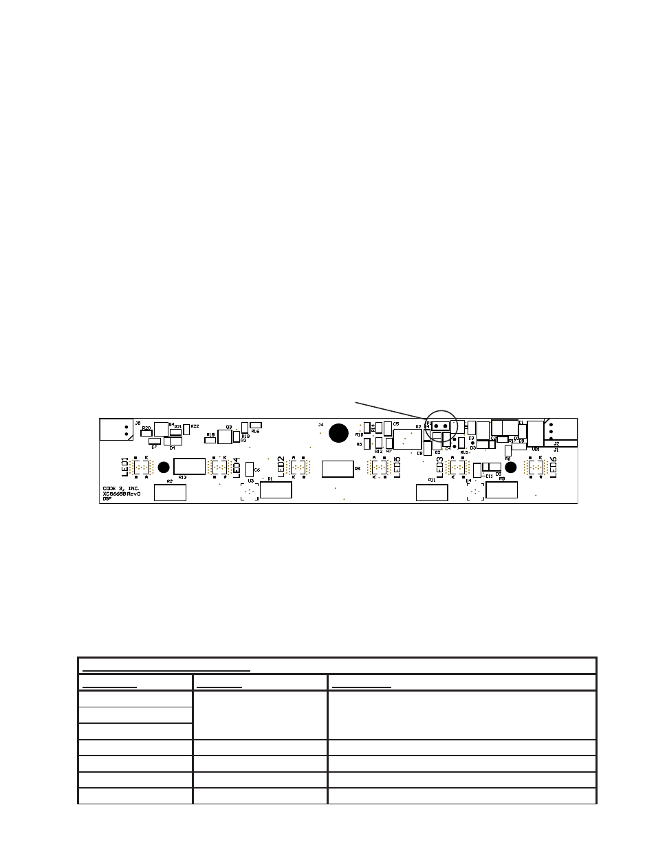
Located on front of
Integrated PCB/Light Engine
Momentarily short and
release to change patterns
Optic removed for clarity
The flash pattern can be changed by shorting the J4 pad with a wire or blade of
a screwdriver (shown below). The lighthead can be reset to the default by short-
ing the J4 pad for greater than 5 seconds and then releasing
The following table shows the functions of the conductors of the 7 conductor cable. Please note that the CC
must be powered (red conductor must have +12VDC) before any of the functions can be enabled. The blue,
orange, and yellow flash activation conductors, when energized, enable the lightheads to be flashed.
Note: All control inputs are +power enabled.
Control Input Function Definition
Wire Color
Function
Description
BLUE (primary)
Flash Activation
Energizes light heads per the pattern chosen by the
end user or, if left unchanged, per the defaults set at the
factory (see table of flash patterns).
ORANGE (secondary)
YELLOW (multi-color)
WHITE
Dimming
Dims lighthead modules
GREEN
Pattern Select
Light Bar Flash Pattern Select Wire & Diagnostic Test
BLACK
Ground
Ground
RED
Power
+12V Input Supply
PriZm II
TM
, Torus
TM
, and TriCore
TM
modules with Central Controller