Code 3 DuoBeam II User Manual
Page 3
3
Utilizing non-factory supplied screws and/or mounting brackets and/or the improper
number of screws may result in loss of warranty coverage on the equipment.
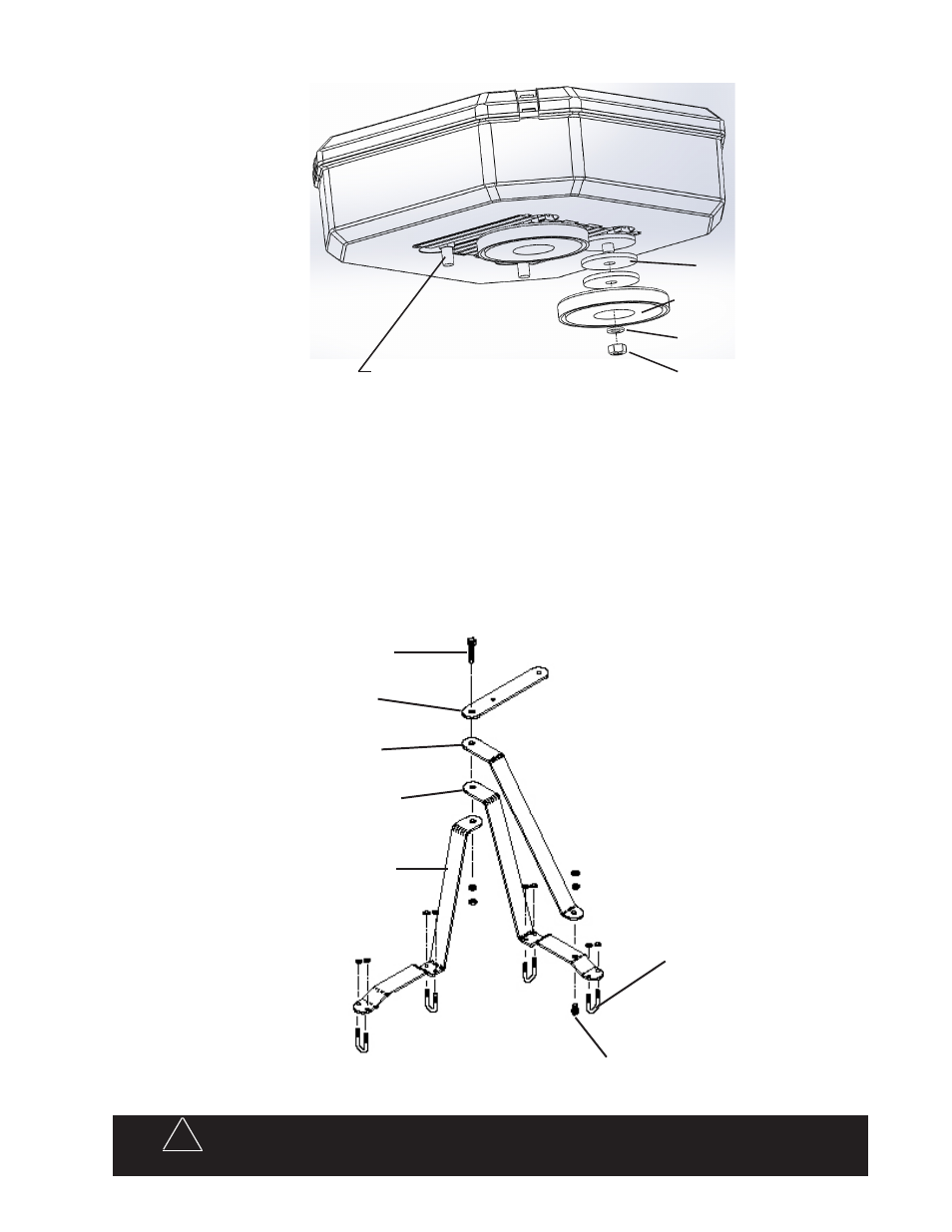
MOLDED SHIM (PN 1064)
RB 80 MAGNETIC BASE (PN 499)
5/16" SPLIT WASHER (PN 245)
5/16-18 SS HEX NUT (PN 244)
MAGNETIC MOUNT
Insert carriage bolts into
track. Place molded shims
over bolts as shown. Attach
magnetic base over bolts.
Place lock washer and nut
on bolt then tighten until
snug.
5/16-18 X 1 1/2" CARRIAGE BOLT (PN 240)
7/16" LONG BOLT
T03807 MOUNTING BRACKET
T03804 MOUNTING BRACKET
T07595 MOUNTING BRACKET
T07595 (IMMBH) OR T03802 (MMBH)
MOUNTING BRACKET
U-BOLT
3/8" LONG BOLT
MIRROR MOUNT BRACKET
1. Assemble the brackets, tighten the 3/8 bolt but leave the 7/16 bolt finger tight at this time.
2. Position bracket assembly on top mirror supports, bracket A on rear support and bracket B on front sup-
port. Note: some mirror designs require reversing bracket A and B. Rotate bracket A as necessary to get
the best fit. Some additional bending of brackets may be necessary in some cases to achieve a satisfac-
tory fit.
3. Attach bracket assembly to mirror supports with U-bolts, position bracket assembly as desired and tighten
U-bolts. The Duo Beam mounting bracket should be parallel to the ground.
Warning!
!