Wiring diagram - with arrowstik, Warning, Option jp1" jumper position – Code 3 CommandStik User Manual
Page 4
4
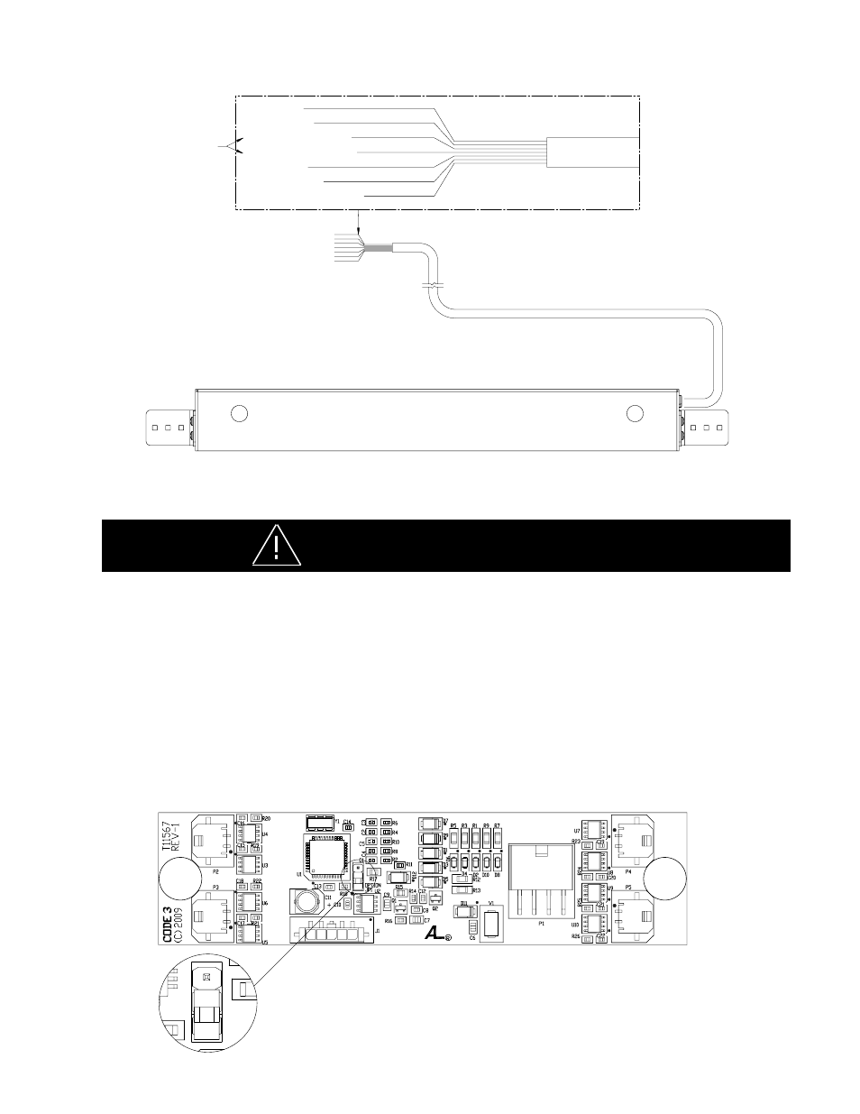
Wiring Diagram - WITH ARROWSTIK®
GREEN (PATTERN SELECT)
WHITE (DIMMING)
RED (POWER)
YELLOW (RIGHT ARROW)
ORANGE (LEFT ARROW)
BLUE (LEVEL 1)
BLACK (GND)
THESE WIRES MAY BE
SWAPPED IF ARROW
DIRECTION IS NOT
AS DESIRED
This Product contains high intensity Torus devices. To prevent eye damage,
DO NOT stare into light beam at close range.
WARNING!
6 HEAD ARROWSTIK W (2) OUTER LIGHT HEADS FLASHING ALTERNATELY
The CommandStik can be configured as a 6 or 8 head ArrowStik. To change the CommandStik from an 8 head ArrowStik to
a 6 Light Head configuration with the (2) Outboard Light Heads flashing alternately, remove the mounting screws that attach
the CommandStik's Cover to the Outer Panel to gain access to the printed circuit board inside (see the exploded view on page
6). Move the Shunt Option Jumper (JP1) on the printed circuit board to the "OPTION JP1" position as shown below. When
configured for a 6 head operation, the (2) Outboard Light Heads will alternate during any ArrowStik mode. Carefully replace the
CommandStik's Cover over the Outer Panel and replace the Cover Mounting Screws.
Note: Be extremely careful to replace the wiring such that you don't pinch a wire when you
replace the CommandStik's Cover. Test the unit to be sure that it works properly.
<---------------"OPTION JP1" Jumper Position