Installation instructions, Wiring instructions, Wiring diagram - standard non arrowstik – Code 3 CommandStik User Manual
Page 3: Warning
3
Installation Instructions
Step 1
Assemble the mounting brackets to the CommandStik with the the supplied 1/4"-20 screws and internal tooth lock washers and
tighten the screws finger tight (see page 6 for orientation).
Step 2
Using the CommandStik assembly as a template, locate the CommandStik in the desired location for the light bar in the vehicles
rear deck area and mark the location of the customer supplied carriage bolts using the square holes in the CommandStik 90 degree mounting
brackets. Note: The square holes in the CommandStik's 90 degree mounting brackets are sized for 1/4-20 carriage bolts.
Step 3
Drill the required mounting holes through the vehicles fabric and sheet metal to provide a hole for the customer supplied mounting
bolts. Note: in many cases some sort of spacer will be required between the vehicle's fabric and it's sheet metal to keep the fabric
from collapsing as you tighten the hardware. The spacer should be made out of a suitable plastic or metal for safety.
Step 4
Install the customer supplied carriage bolts, washers and lock washers through the square holes in the CommandStik's 90 degree
mounting brackets and through the holes in the vehicle's rear deck fabric and sheet metal and tighten all fasteners securely.
Caution: Drilling into the housing of the light bar could damage wiring or other internal components.
Wiring Instructions
It is advisable to leave an extra loop of cable when installing the light bar to allow for future changes or reinstallations. Connect
the black lead to a solid frame ground (earth), preferably the (-) or ground (earth) side of the battery, and the power wire to the +12V
terminal of the battery. Connect the remaining wires as shown below on this page and on page 4.
Larger wires and tight connections will provide longer service life for components. For high current wires it
is highly recommended that terminal blocks or soldered connections be used with shrink tubing to protect
the connections. Do not use insulation displacement connectors (e.g. 3M
®
Scotchlock type connectors).
Route wiring using grommets and sealant when passing through compartment walls. Minimize the
number of splices to reduce voltage drop. High ambient temperatures (e.g. under hood) will significantly
reduce the current carrying capacity of wires, fuses, and circuit breakers. Use "SXL" type wire in engine
compartment. All wiring should conform to the minimum wire size and other recommendations of the
manufacturer and be protected from moving parts and hot surfaces. Looms, grommets, cable ties, and
similar installation hardware should be used to anchor and protect all wiring. Fuses or circuit breakers
should be located as close to the power takeoff points as possible and properly sized to protect the wiring
and devices. Particular attention should be paid to the location and method of making electrical connections
and splices to protect these points from corrosion and loss of conductivity. Ground terminations should
only be made to substantial chassis components, preferably directly to the vehicle battery. The user should
install a fuse sized to approximately 125% of the maximum Amp capacity in the supply line to protect
against short circuits. For example, a 30 Amp fuse should carry a maximum of 24 Amps. DO NOT USE
1/4" DIAMETER GLASS FUSES AS THEY ARE NOT SUITABLE FOR CONTINUOUS DUTY IN SIZES
ABOVE 15 AMPS. Circuit breakers are very sensitive to high temperatures and will "false trip" when
mounted in hot environments or operated close to their capacity.
WARNING!
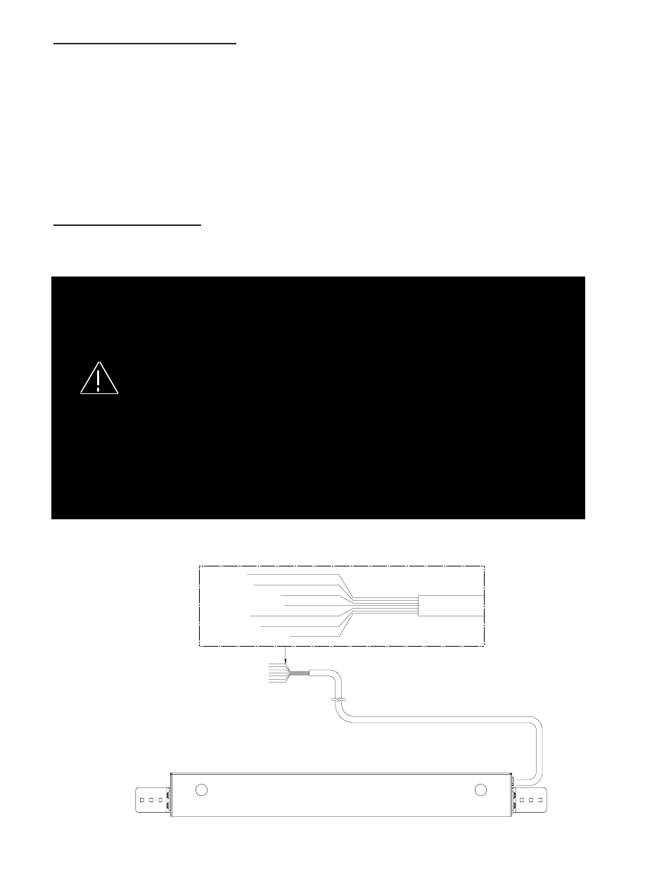
Wiring Diagram - STANDARD NON ARROWSTIK®
GREEN (PATTERN SELECT)
WHITE (DIMMING)
RED (POWER)
YELLOW (LEVEL 3)
ORANGE (LEVEL 2)
BLUE (LEVEL 1)
BLACK (GND)
FUSE WITH CUSTOMER SUPPLIED 10 AMP FUSE