Continued flasher installation (model 940) – Code 3 930 and 940 Flashers User Manual
Page 5
5
NOTE: For continued Alley light flash while in low beam, do not connect Terminal 1.
8)
Connect the negative (-) post of the battery, or other good ground(earth), to Terminal 11 of the
Flasher Unit.
9)
Connect a user supplied switch between the positive (+12VDC) source and Terminal 3 of the
Flasher Unit. This switch will override the flash feature and cause the Left Alley Light
to operate in steady burn mode.
10)
Connect a user supplied switch between the positive (+12VDC) source and Terminal 4 of the
Flasher Unit. This switch will override the flash feature and cause the Right Alley Light
to operate in steady burn mode.
If you are installing the Model 930 flasher, proceed to Testing the Flasher on Page 6. If you are installing
flasher Model 940 continue with step 11 below.
Continued Flasher Installation (Model 940)
To install the Model 940 as a Takedown / Alley Light flasher, complete the above outlined steps and then
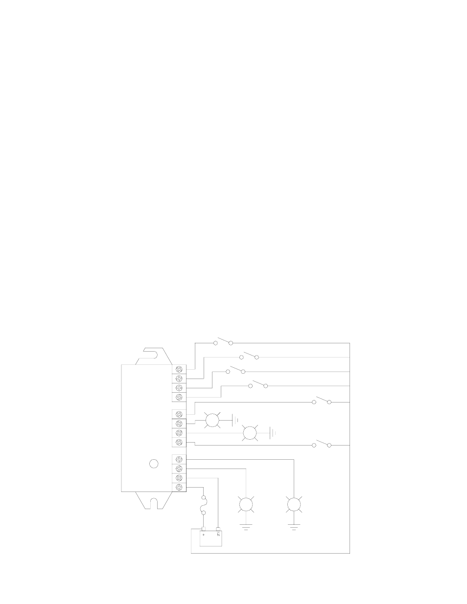
refer to Figure 2 for the following steps:
11)
Connect the Right Takedown Light to Terminal 7 of the Flasher Unit.
12)
Connect the Left Takedown Light to Terminal 6 of the Flasher Unit.
13)
Connect a user supplied switch between the positive (+12VDC) source and Terminal 5 of the
Flasher Unit.
14)
Connect a user supplied switch between the positive (+12VDC) source and Terminal 8 of the
Flasher Unit. This switch will override the Takedown flash feature and cause the Takedown
Lights to operate in steady burn mode.
Double check all of your connections then refer to the section on testing the circuit.
-
-
-
-
-
-
-
-
-
-
-
-
U6F@Ã9PXIÃGDBCUÃÅ7Å
U6F@Ã9PXIÃGDBCUÃÅ6Å
U6F@Ã9PXIÃAG6TCÃ@I67G@
6GG@`ÃGDBCUÃÅ7ÅÃTU@69`Ã7VSI
6GG@`ÃGDBCUÃÅ6ÅÃTU@69`Ã7VSI
6GG@`ÃGDBCUTÃAG6TCÃ@I67G@
9DT67G@Ã8VUPAA
U6F@Ã9PXIÃTU@69`Ã7VSI
%$77(5<
!PÃ6HQÃAVT@
#Ã6XBÃHDI
6GG@`
GDBCUÃÅ6Å
GDBCUÃÅ7Å
6GG@`
FIGURE 2: WIRING DIAGRAM FOR 940
LIGHT BAR FLASHER INSTALLATION