Flasher installation, Flasher installation (model 930) – Code 3 930 and 940 Flashers User Manual
Page 4
4
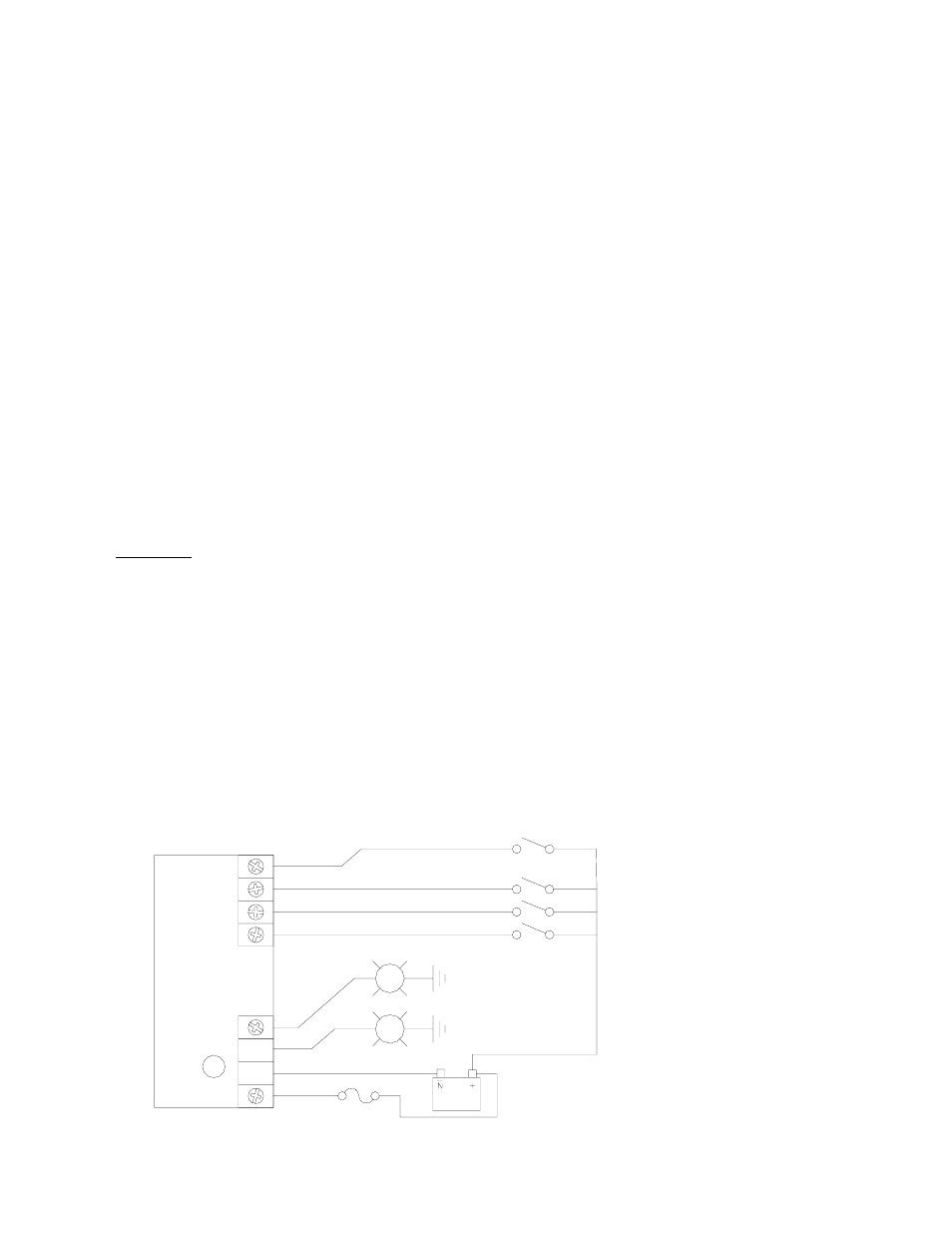
FIGURE 1: WIRING DIAGRAM FOR 930
LIGHT BAR FLASHER INSTALLATION
Terminal 10 - Output 2: 8 amps Maximum.
Terminal 11- To Battery Negative (-).
Provides the unit with ground (earth) to complete the circuit. For best results, connect directly to the
negative (-) terminal of the battery, or in light bar applications, connect to the light bar frame ground
(earth).
ro
tect all wiring.
Terminal 12- Battery Positive (+12VDC).
Supplies Outputs +12VDC. The Unit should be fused with a user supplied 20 amp. fuse and wired with
#14 AWG wire minimum.
Flasher Installation
Flasher Installation (Model 930)
To install the Model 930 as an Alley Light flasher, refer to Figure 1 while following the steps below:
NOTE: Use #14 AWG wire (minimum) for all connections.
1)
Mount the Flasher Unit in a convenient location inside the light bar or in the trunk (or console)
near the lighting control switch box.
2)
Locate the +12V supply wire inside the light bar (or near the lighting control switch box) and
connect a 20 amp. fuse and holder in-line between the +12V source and Terminal 12 of the
Flasher Unit.
CAUTION: Leave the fuse out of the fuse holder until ready to test the circuit.
3)
Install a user supplied switch in a convenient location near the driver.
4)
Connect the user supplied switch between the positive source (+12VDC) and Terminal 2 of
the Flasher Unit.
5)
Connect the Right Alley Light to Terminal 10 of the Flasher Unit.
6)
Connect the Left Alley Light to Terminal 9 of the Flasher Unit.
7)
(OPTIONAL) Connect the vehicle’s low beam switch to Terminal 1 of the Flasher Unit.
#Ã6XBÃHDI
!PÃ6HQÃAVT@
AG6TC@SÃ9DT67G@
SDBCUÃ6GG@`ГTU@69`Г7VSI
-
-
-
-
GrsÃ6yyr
AG6TC@SÃPI
-
-
-
-
SvtuÃ6yyr
%$77(5<
G@AUÃ6GG@`ГTU@69`Г7VSI