Code 3 87, 88, 89 Series Perimeter Lights User Manual
Page 4
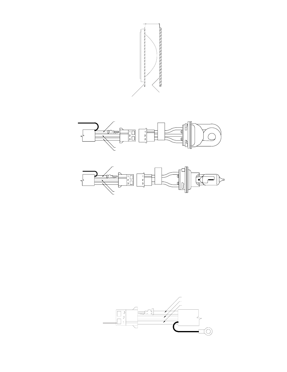
INTERIOR WALL OF VEHICLE OR
NEAREST OBSTACLE DIRECTLY BEHIND
LIGHT HEAD
2.000 MINIMUM
EXTERIOR WALL OF VEHICLE
FIGURE 2
FIGURE 3
1.
Select the desired mounting location for the light head assembly.
2.
Verify 2 inches minimum free clearance behind the mounting surface, see Figure 2.
3.
Cut the opening and drill the holes, use Figure 1 template or the trim bezel if your light head is so equipped.
4.
With one end of the cable at the light head mounting location, route the three wire cable to the Power
Supply.
5.
At the light head end of the cable, insert the 3 AMP sockets into the AMP socket housing as shown in Figure
3. Cut the shield wire flush with the jacket. (Halogen Lamp Assemblies are shown. Procedure is the same
for Strobe Lamp Assembly.)
6.
Allow 3 inches minimum slack at the light head to facilitate lamp assembly replacement. Secure the cable.
7.
At the power source end of the cable determine if the cable length is acceptable. If a shorter length is
required, coil the cable and tie with an electrical tie.
8.
Insert the 3 AMP sockets into the AMP socket housing as shown in Figure 4.
9.
Crimp the #8 ring terminal to the shield wire and attach to nearest grounded structure.
RED WIRE - HIGH VOLTAGE
BLACK WIRE - GROUND (EARTH)
SHIELD WIRE
(CUT FLUSH)
FIGURE 4
BLACK WIRE - GROUND (EARTH)
THIS END TO POWER
SUPPLY
SHIELD WIRE (Not used on
Model 88.)
RED WIRE - HIGH VOLTAGE
(STROBE)
12/24 VDC (HALOGEN)
WHITE WIRE - TRIGGER
WHITE WIRE - TRIGGER
SHIELD WIRE
(CUT FLUSH)
RED WIRE - +12/24 VDC
BLACK WIRE - (NOT USED)
WHITE WIRE - GROUND(EARTH)
4