Warning – Code 3 420 Mini Bar Series User Manual
Page 5
5
LED X CORNER LED MODULE
Operating Specifications for Corner LED module:
Operating Voltage: 10-16 VDC, Reverse Polarity Protection
Current Draw : Red/Amber - .5A avg @ 12.8 Volts
Blue
- .8A avg @ 12.8 Volts
Available Colors - Red, Blue, and Amber
Master/ Slave Operation
Each 360 degree corner module consists of a "master" and a "slave" driver circuit board, 360 degree
optics
and LED light engines along with a dual integrated heatsink bracket.
The "master" circuit board must always be powered for the "slave" to flash. The flash pattern for each
corner pair can be selected by moving jumpers J1 and J2 on the "master" to the appropriate position on
the circuit board. The module is set-up for "Cycleflash" as a standard. The following chart describes the
pattern for each jumper position;
360 Degree Module Flash Pattern - Table 1
Place jumpers as shown to select flash pattern:
See Figure 2, page 6, for jumper installation.
Jumper Position
Flash Pattern
Description
J1 J2
Bottom (on)
Bottom (on)
N/A
Bottom (on)
Top (off)
N/A
Top (off)
Bottom (on)
Quad Flash
Four Pulses per flash @ 60 fpm min
Top (off)
Top (off)
Cycle-Flash
Cycles through various patterns @ 70 fpm avg.
Both heads will be in the mode selected
TM
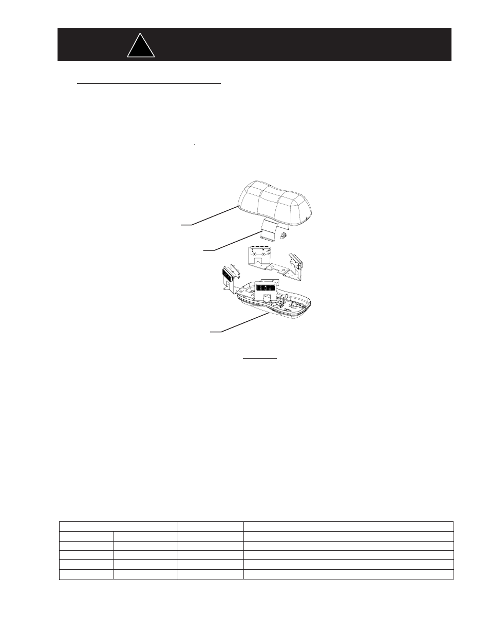
WIRE GUARD SHROUD
(1)
425 BEACON COVER LENS
(1)
LED 425 BASE (1)
Figure 1
This Product contains high intensity LED devices. To prevent eye damage,
DO NOT stare into light beam at close range.
WARNING!
!