Installation instructions - cont, Troubleshooting, Wiring: cels citadel version wiring – Code 3 2015 Tahoe Citadel User Manual
Page 4: Standard citadel version wiring, Troubleshooting guide, Warning
4
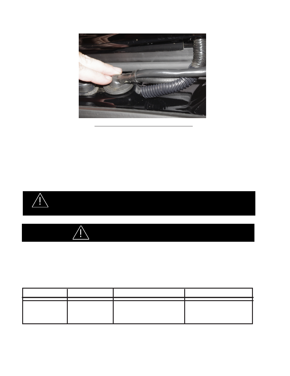
Installation Instructions - Cont:
FIGURE -8 CELS VERSION CABLE SHOWN
Step -11. Route the cable/harness the rest of the way as desired!
Step -12.
Wiring:
CELS Citadel Version Wiring:
The light heads in the CELS version of the Citadel are all STEADY
BURN ONLY and require the CELS controller for power, lighting sequence, and flash patterns. See the Instruc-
tion Manual for the CELS -CC Housing for wiring connections and flash patterns.
Standard Citadel Version Wiring:
Red - Power---Black - Negative (Ground)---The Blue wire is the
Program Wire!
Troubleshooting
All Citadel Products are thoroughly tested prior to shipment. However, should you encounter a problem during installation or during
the life of the product, follow the guide below for information on repair and troubleshooting. Additional information may be obtained
from the factory technical help line at 314-996-2800. Follow the guide below for information on repair and troubleshooting.
TROUBLESHOOTING GUIDE
QUESTIONS
POSSIBLE CAUSE
A. Bad power/ground
Connection.
B. Defective module.
SOLUTION
A. Fix connection.
B. Replace module
N/A
PROBLEM
XT Module not operat-
ing when powered.
This Product contains high intensity LED devices. To prevent eye damage,
DO NOT stare into light beam at close range.
WARNING!
DO NOT APPLY 12 VOLTS DIRECTLY TO THE CITADEL WIRES AFTER IT IS CONNECTED TO THE CELS
CC BOX. IF THE CITADEL IS A COMPONENT OF THE CELS SYSTEM THE CC BOARD OR THE LIGHT
HEADS COULD BE DAMAGED BY APPLYING 12 VOLTS TO THE CC OUTPUTS!
WARNING!