Installation instructions – Code 3 2015 Tahoe Citadel User Manual
Page 2
2
Installation Instructions:
Tools Needed------10 mm Socket-------T25 Torx Driver-----Torque Wrench
NOTE: If you have purchased a CELS Citadel, skip steps 1 through 3 below!
Step -1. For the Standard version of the Citadel the light heads are smart versions (Flashing) light heads. Each light
head will need to be programmed to set the desired flash pattern. See the supplied instruction sheet that comes with the
light heads for setting and changing the light head flash patterns.
Step -2. Thread the wire connectors from each of the light heads through the oblong holes in the mounting brackets
then mount the light heads on the Citadel Brackets using the supplied mounting screws. Making sure the longest side
of the Citadel Wiring Harness is attached to the driver's (LEFT) side bracket, plug the light heads into the terminals of
the wiring harness. The length of the wires determines which plug gets connected to which light head (The longest wire
plugs to the light head farthest out from the center of the vehicle then the next longest plugs to the next light head etc).
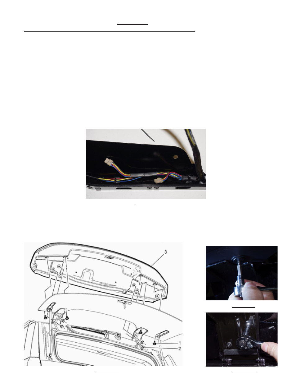
Step -3. Using the supplied square adhesive mounting bases and zip ties, attach the Citadel Wiring Harness to the
inside of the Citadel mounting brackets to make sure the wires will be safely tucked inside the brackets when the instal-
lation is complete (See Figure -1). Important Note: Thoroughly clean all locations where the square adhesive
mounting bases will be installed with the supplied alcohol pads before adhering the mounting bases to the
brackets! Allow the alcohol to dry completely before applying the adhesive bases.
FIGURE -1
Step -4. Begin the installation by removing the (2) #25 Torx Screws on one side of the vehicle (See Item #1 in Figure -2
and see Figure -3). Note: It is highly recommended that you install one side of the Citadel at a time to keep the
rear glass and spoiler in alignment!
Step -5. Loosen the (2) 10 mm nuts on one side (See Item #2 in Figure -2 and see Figure -4).
FIGURE -3
FIGURE -2 FIGURE -4