Salter Brecknell CP80 User Manual
Page 9
CP80 User Guide Page 9 of 11
1
4
2
6
3
5
7
CONNECTIONS AND EMC PRECAUTIONS
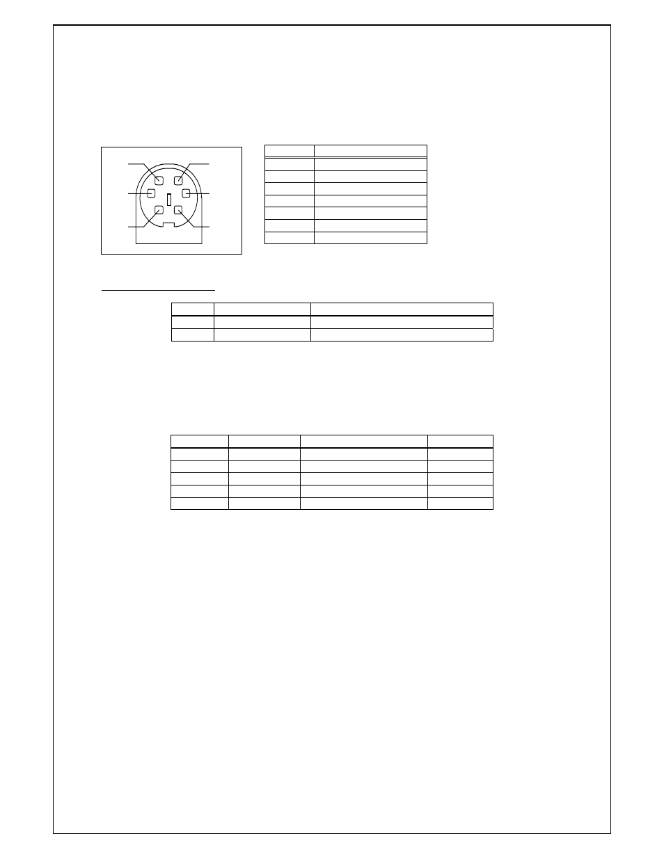
7.1 CONNECTOR
DETAILS
A single socket on the rear of the printer combines all data and charger functions.
Printer side:
Hosiden TCS7167 6-way Socket (mini-DIN style)
User side:
Hosiden TCP7160 6-way Plug & Cable or equivalent
Pin
Function
1 TxD
Data
Output
2 BUSY
Output
3 RxD
Data
Input
4
Optional Baud Select
5
Ground ( 0V)
6 No
Connection
Screen Frame
Ground
Connector viewed from rear of printer.
PSU Jack Socket Detail
Pin Dimension
(mm)
Function
Inner
Inside Ø 2.1
Positive 9-36VDC Input
Outer
Outside Ø 5.5
Negative / 0V Common
The maximum insertion length is 12 mm.
7.2
TYPICAL 9 PIN RS232 DATA CABLE CONFIGURATION
A D-9 Female socket with the following pinout:
D-9 Pin
Name
Function (refers to PC)
CP80 Pin
Shell FGND
Frame
Ground
Screen
3
TxD
Serial Data Output
3
2
RxD
Serial Data Input
1
6 & 8
CTS & DSR
Busy Input
2
5
SGND
Signal Common 0V
5
7.3
POWER SUPPLY DETAILS
The CP80 is directly powered through the power jack at the rear of the printer.
The printer is designed for direct connection to a +12V or +24V vehicle battery.
Alternatively, the user may make their own power supply arrangements as described in Section 7.4.