Installing transport handle – Salter Brecknell CS-200M User Manual
Page 4
4
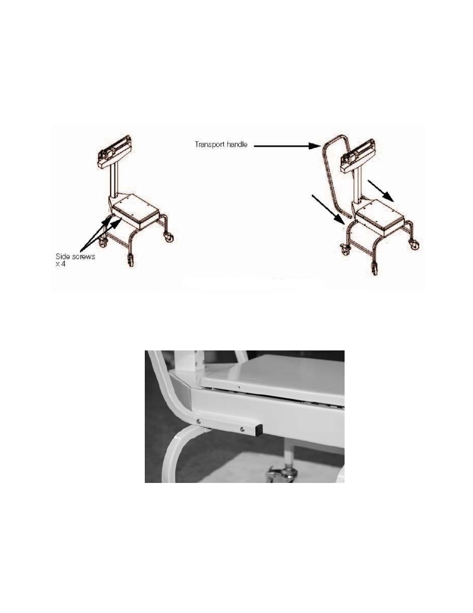
Installing Transport Handle
Once the pillar and beam are attached to the scale support frame and secured, it’s time to attach the
transport handle to the scale support frame (transport handle is illustrated in Figure 8).
1. Remove the four side screws (two on each side as shown in left hand side of Figure 7) from the
scale support frame and set aside. The transport handle will attach to the scale support frame using
those screws.
Figure 7. Transport Handle Installation
2. Insert the transport handle into the two sides of the scale support frame as shown in right side of
Figure 7.
3. Insert and tighten the four screws using a phillips screwdriver as shown in Figure 8.
Figure 8. Insert and Tighten Four Screws for Securing the Transport Handle to the Scale Support Frame
The transport handle should fit snuggly against the scale support frame.
- PB500 (4 pages)
- PB250 (12 pages)
- MB2610 (4 pages)
- MBS Series (14 pages)
- 302BP (6 pages)
- 304BP (26 pages)
- 308BP (27 pages)
- APD-100 (36 pages)
- CB100 (8 pages)
- ESA Series (14 pages)
- LPS30 (18 pages)
- PC150 (13 pages)
- SP60 (9 pages)
- 3700LP (20 pages)
- C3235 (16 pages)
- C3255 (18 pages)
- C3225 (40 pages)
- B140 (32 pages)
- B120 (19 pages)
- B130 (22 pages)
- 610 (23 pages)
- 630 (24 pages)
- 650 (43 pages)
- B220 (24 pages)
- B225 (44 pages)
- CS Series Crane (12 pages)
- 3800LP Series Calibrated with SBI-505 LED Indicator (22 pages)
- 405 (12 pages)
- LPS150 (30 pages)
- GP100 (13 pages)
- S100 (17 pages)
- PS150 (15 pages)
- S122 (63 pages)
- 6702 (28 pages)
- 6712 (24 pages)
- PS250 (28 pages)
- PS500 (19 pages)
- PS1000 (38 pages)
- PS3000HD (18 pages)
- SBI140 (35 pages)
- SBI100 (34 pages)
- SBI-521 (82 pages)
- 200 Series (47 pages)
- 200SL (2 pages)
- 400ES (30 pages)