Introduction, Installation and wiring, Keyboard functions – Salter Brecknell SP100 User Manual
Page 3
02/18/04
3
Introduction
The SP Series Digital Bench Scale is a
compact, legal for trade scale with remote digital
indicator. Housed in a standard black polymer
case, the indicator displays its numerals on a
bright VFD screen. The base unit features a
removable stainless steel platform, an RS-232
serial communication port, and adjustable feet
for leveling.
The SP Series uses full duplex RS-232 serial
format for communication with many types of
attached support equipment. The unit can trans-
mit data on demand, or continuously in several
popular data protocols to match a wide variety of
printers, remote displays, or personal computers.
If you plan to use your scale with equipment
other than a PC, you may have to alter the serial
communication parameters which are embed-
ded in the User Menu.
The User Menu is accessed through the front
panel keys. Complete directions, including a
graphical road map, are found in the Configura-
tion section of the manual.
Installation and Wiring
Unless you wish to interface to a device other
than a PC, no wiring is necessary. Simply con-
nect the indicator to the scale platform, plug in
the AC adapter, and turn the unit on. If the swivel
indicator option was ordered, the stainless steel
post may be mounted to the bottom of the base
with the hardware provided. Alternately, it may
be mounted to a table or bench. In general,
please allow a 20 minute warm up period before
using the scale.
If interfacing to a PC, simply connect the optional
null modem cable to a serial port (e.g. COM 1)
on your PC. If your computer has a 25-pin serial
port, a standard 9-pin to 25-pin adapter, such as
the type used for a mouse, may be used and is
readily available at your local computer supply
retailer.
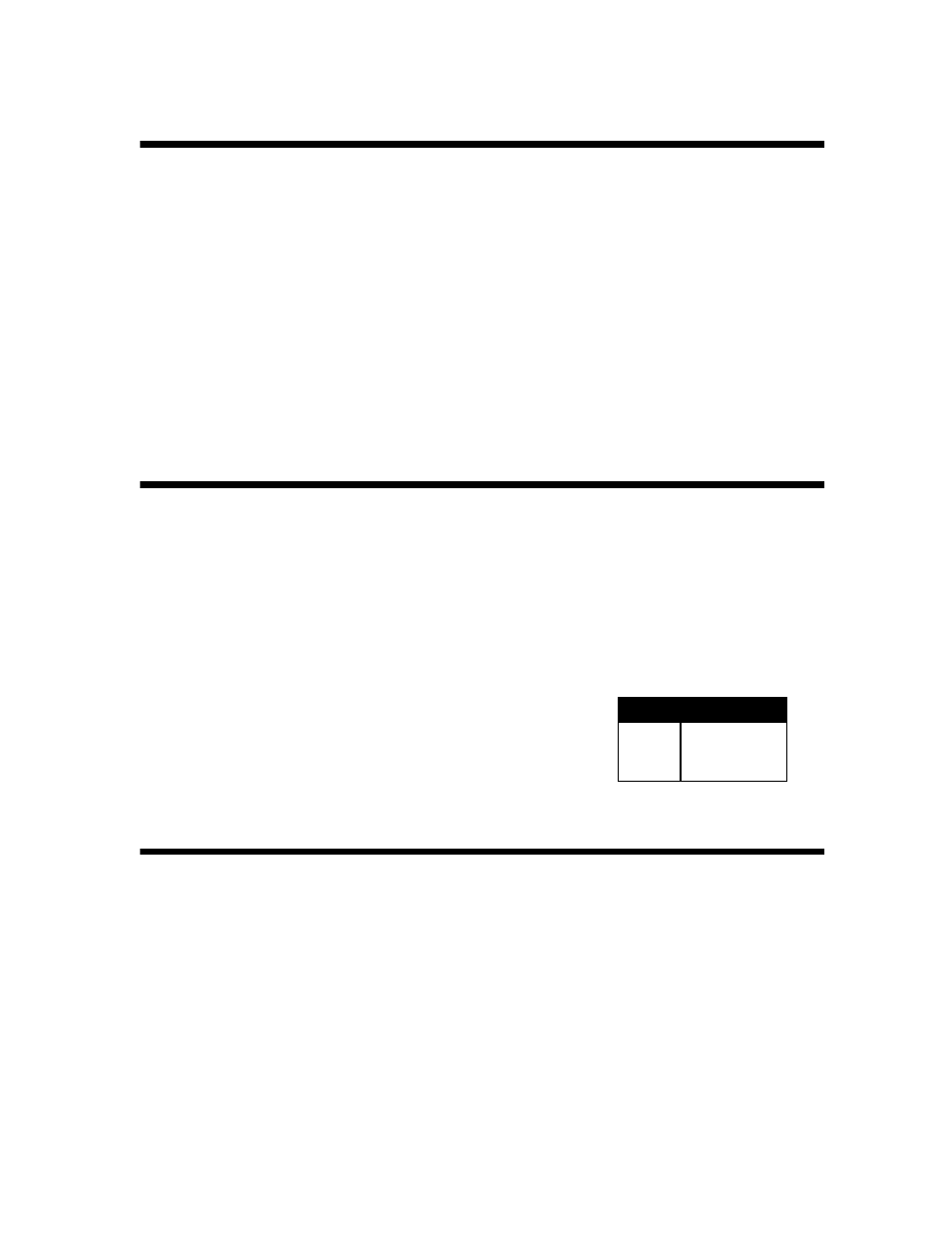
If interfacing to a serial device other than a PC, you may have to wire
your own cable to communicate with that device. If so, refer to the 9-
pin connector pinout shown at right.
Pin No.
Pin Name
2
Receive Data
3
Transmit Data
5
Signal Ground
9-Pin Connector Pinout
Keyboard Functions