Charles Industries 31929E User Manual
Page 6
Section 319–29E–202
6
S3
1
2
S4
DISABLE
A
I
S
S1
PWR
7.5 7.5
1
2
O
N
LP
SC
S2
LOS
ALM
R
C
V
X
M
T
R
P
T
M
O
N
R
P
T
M
O
N
WESCOM
PWRG
T1
NIU
3192-9E
91-31929E
0.6V
ISS. 2
FA
ESF
NET
LOS
LB
CI
LOS
MLB
r
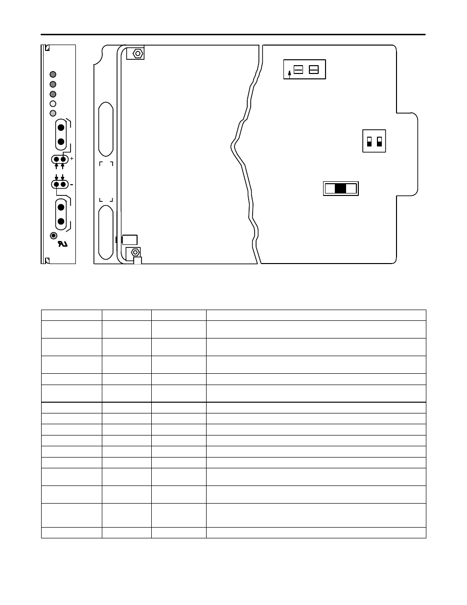
Figure 6. 3192–9E Front Panel Features and Options Location
Table 2. 3192–9E Front Panel Options Description
Feature/Option
Location
Description
Function
FA (Fuse Alarm)
Front Panel
Red LED
Indicates that the internal fuse on the 3192-9E has opened. The internal fuse is
not field replaceable.
NET LOS (Loss of
Signal)
Front Panel
Red LED
Continuous: Indicates LOS (Loss Of Signal) from the network side.
Flash: Indicates receipt of AIS from the network side.
CI LOS (Loss of
Signal)
Front Panel
Red LED
Continuous: Indicates loss of signal from the customer interface side.
Flash: Indicates sending of AIS to the network side.
LB (Loopback)
Front Panel
Amber LED
Indicates that the unit is in the Loopback State.
ESF (Extended
Superframe)
Front Panel
Green LED
Indicates ESF Framed signal from the network.
RCV RPT
Front Panel
Bantam Jack
Isolates the DSX allowing access to repeater RCV DSX (OUT).
RCV MON
Front Panel
Bantam Jack
RCV DSX (OUT) monitor jack.
+ Test Pins
Front Panel
Pin Jack
Used for measuring span current and voltage.
– Test Pins
Front Panel
Pin Jack
Used for measuring span current and voltage.
XMT RPT
Front Panel
Bantam Jack
Isolates the DSX, allowing access to repeater XMT DSX (IN).
XMT MON
Front Panel
Bantam Jack
XMT DSX (IN) monitor jack.
S1
PC Board
3 Position Slide
Switch
3Ćposition switch to select either PWR (line powering), SC (Sealing Current) or
LP (Looped Simplex) CI side power modes.
S2
Front Panel
Front Panel Push-
button Switch
S2 is the recessed front panel MLB (Manual Loopback) pushbutton switch to
manually activate or deactivate loopback.
S3
PC Board
2 Section Dip
Switch
S3–1 enables or disables a LOS condition alarm detected by CI side.
S3–2 enables or disables the operation of the Customer Receive Side AIS gen-
erator
.
S4
PC Board
2 Section Switch
Adjusts the transmit pad, allowing a transmit path loss of 0, 7.5 or 15 dB.