Charles Industries 31929E User Manual
Page 10
Section 319–29E–202
10
6.2
S2 — Front Panel MLB Push Button
S2 is a recessed, front-panel push-button switch used to manually activate or deactivate loopback. Momentarily
depress the MLB (Manual Loopback) push-button switch to activate or deactivate a loopback condition.
6.3
S3 — LOS ALM and AIS Enable/Disable
S3 is a two-section dip switch that interacts with the transmit and receive signal detectors on the 3192–9E.
6.3.1.
S3–1 — LOS ALM
S3–1 is used to enable or disable sending a LOS (Loss of Signal) condition alarm to the shelf alarm buss. The
LOS condition is detected by the Customer Interface Side Signal detector. For more information, see Paragraphs
3.10 and 3.11, and Figure 6.
6.3.2.
S3–2 — AIS Generator
S3–2 is used to enable or disable operation of the Customer Receive Side AIS generator that sends AIS toward
the network upon LOS from the CI.
6.4
S4 — XMT Pad dB
S4 is a 2-section switch used to adjust the transmit pad, allowing transmit path losses of 0, 7.5 and 15dB. See
Figure 6.
7.
TESTING
The procedure shown in Table 3 can be used to verify operation of the 3192–9E for pre-service checkout.
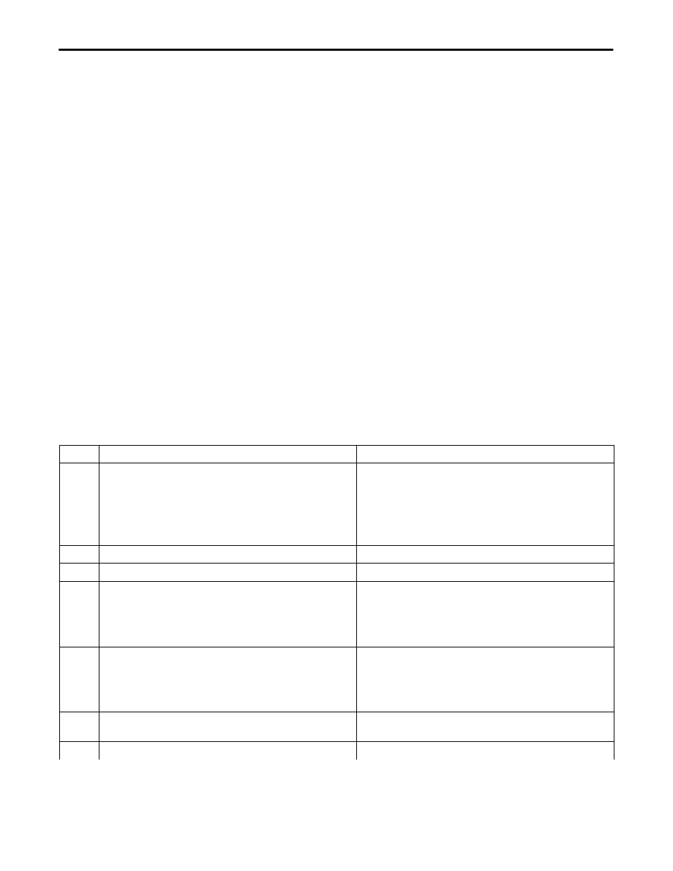
Table 3. 3192–9E Verification of Operation and Performance Test Procedure
Note: Requires TBERDĆ209 Digital Transmission Test Set or Equivalent.
Step
Action
Action
1.
Option the 3192–9E as follows:
Set Switch S3–2 (AIS) to the DISABLE position.
Set Switch S3–1 (LOS ALM) to the DISABLE posi-
tion.
Set Switch S1 (PWR) to the LP position.
Set Switch S4 (XMT LBO) for 7.5dB.
2.
Insert the 3192–9E into the shelf assembly.
3.
Disconnect the CPE at the Network Interface.
4.
Connect the Digital Transmission Test Set
(TBERD-209) to the 3192–9E via its front panel
jacks as follows:
TBERD-209 SEND to XMT RPT.
TBERD-209 RCV to RCV RPT.
5.
Set the TBERD-209 to transmit an all Zeros pat-
tern.
All the 3192–9E front panel LEDs should be off
except for the NET LOS and CI LOS LEDs which
should be on. This indicates NO signal from the
network or CPE equipment. The TBERD-209
should be receiving a NO signal condition.
6.
Condition the TBERD-209 to send an AIS (all
ones) signal.
The 3192–9E NET LOS LED should flash.
7.
Change the TBERD-209 to send a QRSS pattern.
The 3192–9E NET LOS LED should extinguish.