Application engineering – Charles Industries 31929E User Manual
Page 3
Section 319-29E-202
3
2.
APPLICATION ENGINEERING
The 3192–9E is ideally suited for use in provisioning T1 High Capacity Digital Service (HCDS) from lightwave-fed
building Remote Terminals located at customer premise locations. See Figure 2 for a typical application. The
3192–9E, used as adjunct equipment to the Lightwave Multiplexer, provides transmission loopback for mainte-
nance activities. In addition, the 3192–9E can be optioned to provide a 60mA constant current power source to-
wards the network interface, which can be used to power the customers’ Channel Service Unit (CSU). This ser-
vice arrangement is typical in MPOP (Minimum Point Of Presence) applications.
The 3192–9E is intended to be co-located with the lightwave transport equipment and serves to extend the nor-
mal DSX range of that equipment. The 3192–9E provides a fixed DSX pre-equalizer for 0 to 110 feet of cable. In
the transmit direction the unit provides variable pads for level coordination toward the CPE. The 3192–9E can
accommodate up to 21dB of cable loss between the customer’s CSU and the 3192–9E.
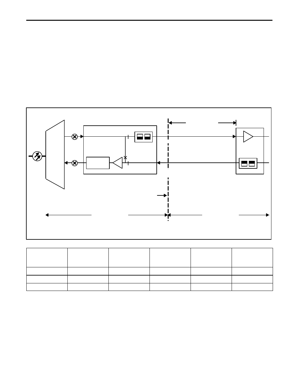
Figure 3 shows a typical 3192–9E application with associated transmission levels.
Note:
Range is limited to maximum cable loss of 21.0db. See table below for maximum cable length at
various cable gauges.
–1.5dB
–1.5 To
–22.5dB
Pre
Equalizer
0.0
DSX–1
Lightwave
Multiplexer
3192–9E Powering T1 NIU
0.0
T1 CSU
LBO
LEC Equipment
CPE Equipment
Customer
Wiring
Maximum
Loss 21.0dB
(See NOTE)
–1.5dB
-1.5 To
-22.5dB
Customer
Network
Interface
Note:
Signal Levels Referenced
To 3V Base-To-Peak
CABLE @ 130 F
AERIAL - PIC
MAXIMUM
LENGTH -KF
TOTAL DCR
@ MAXIMUM
REFERENCE
LOSS - dB/KF
REFERENCE
LOSS - OHMS/
KF
REFERENCE
MAXIMUM
LOSS
22 GA-CU
4.29 KF
78 OHMS
4.9 dB/KF
18.3 OHMS
21.0dB
24 GA-CU
3.44 KF
100 OHMS
6.1 dB/KF
29.2 OHMS
21.0dB
26 GA-CU
2.56 KF
119 OHMS
8.2 dB/KF
46.7 OHMS
21.0dB
Figure 3. 3192–9E T1 Powering NIU Typical Configuration
2.1
Customer Interface Powering Options
The 3192–9E provides three, switch-selectable, CI (Customer Interface) side power modes: line powering, seal-
ing current, and looped simplex. See Part 6 for more information.
2.2
System Power Engineering
The 3192–9E generates all necessary voltages for its operation from a –48V (nominal) battery input source. The
3192–9E contains an internal high efficiency DC–DC converter to minimize input current, and consequently, maxi-
mize battery reserve time in the remote terminal assembly.