AVer FD1020 user manual User Manual
Page 17
11
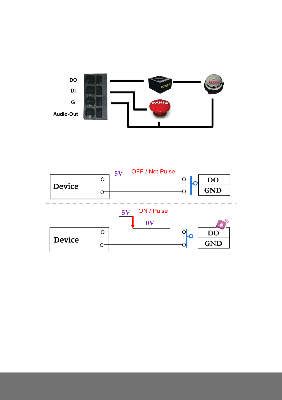
4. I/O Configuration
a. Connect the G (GND) & DO pin to the external relay (buzzer) device.
b. Connect the G (GND) & DI pin to the external trigger device.
When no event occurs, the DO output is 5V (DO and GND are disconnected). When the camera
detects events it will trigger and external alarm, DO output is 0V (DO and GND are connected).
If you select N.O on Input sensor setting, when the switch contacts are opened, the camera input
alarm will be triggered and will execute the action user has set, for example, send a snapshot to
E-mail address.
See also other documents in the category AVer Camcorders:
- PL50 user manual (46 pages)
- W30 user manual (44 pages)
- W30 quick guide (2 pages)
- U15 (2 pages)
- U10 (2 pages)
- F55 On-screen Display (189 pages)
- F55 Remote Control (61 pages)
- F50 user manual (47 pages)
- F50 quick guide (2 pages)
- F50HD user manual (51 pages)
- F50HD quick guide (2 pages)
- F30 user manual (45 pages)
- F30 user manual (43 pages)
- F17HD+ (40 pages)
- CP135 user manual (27 pages)
- CP155 quick guide (4 pages)
- 315AF user manual (48 pages)
- 315AF quick guide (4 pages)
- M70 (45 pages)
- M50(355AF) user manual (44 pages)
- M50(355AF) user manual (43 pages)
- M50(355AF) quick guide (4 pages)
- M30(310AF) user manual (27 pages)
- VP-1 (16 pages)
- VP-1HD (40 pages)
- TabCam user manual (27 pages)
- SPB350+ (24 pages)
- CP355 user manual (33 pages)
- CP355 user manual (30 pages)
- CP155 user manual (27 pages)
- CP155 user manual (30 pages)
- CP300 (192 pages)
- CP150 user manual (26 pages)
- CP150 quick guide (2 pages)
- CP130 user manual (23 pages)
- 300AF user manual (144 pages)
- 300AF user manual (170 pages)
- 300AF user manual (30 pages)
- 300AF quick guide (2 pages)
- SPB370 user manual (27 pages)
- SPB350 quick guide (2 pages)
- SPB350 user manual (25 pages)
- SPC300+ (24 pages)
- SPC300+ (97 pages)
- FX2000 (56 pages)