3 back panel, Back panel – AVer MOB1304-NET User Manual
Page 9
3
1.3
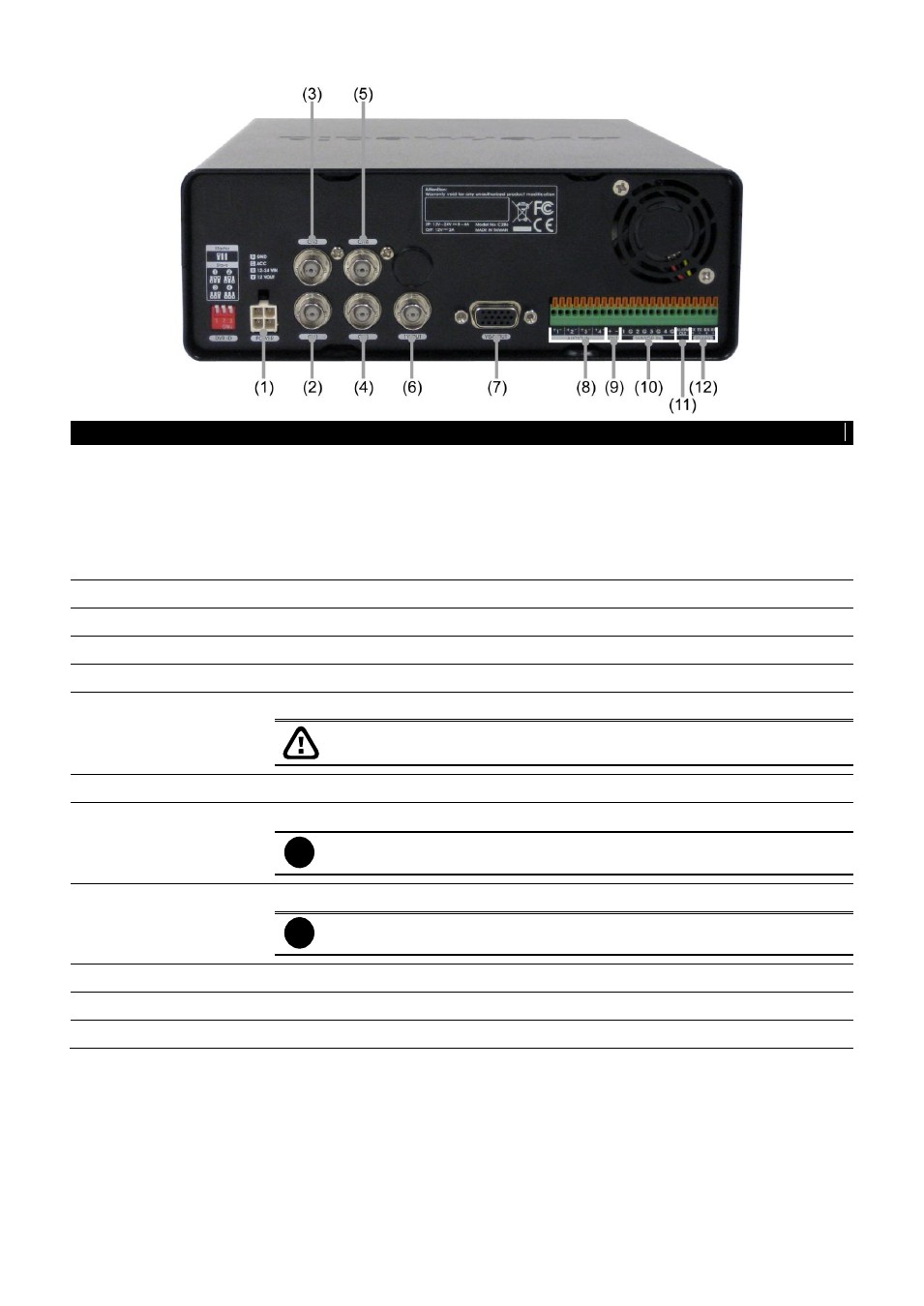
Back Panel
Name
Function
(1) Power cable
Connecting the power cord. The power cord divide into 4 lines and each line has
sticker on it for function description.
GND (Black): Power connecting negative(-)and camera negative(-)
12V~24V(Red): Power connecting positive(+)
ACC(Green): Connect with the ACC line of vehicle
12V Out(Yellow): Camera connecting positive(+)
(2) CH1
Input the video camera signal and display it on channel 1
(3) CH2
Input the video camera signal and display it on channel 2
(4) CH3
Input the video camera signal and display it on channel 3
(5) CH4
Input the video camera signal and display it on channel 4
(6) Video Out (BNC)
Output the video signal to a TV(Call Monitor)
The DVR unit supports dual video output
– Video Out and VGA Out.
(7) VGA Out
Output the video signal to a LCD monitor
(8) Audio In
Input the audio signal from a microphone or audio input device.
i
Microphone with its own power supply is necessary and the internal
amplification must be used.
(9) Audio Out
Output the audio signal to a speaker
i
The audio out device with its own power supply is necessary.
(10) Sensor In
Support 4 sensor device
(11) Alarm Out
Support 1 relay device (Relay: 1A @ 125V AC/30V DC)
(12) RS485
For PTZ camera connection