Making the connections, Rear panel – AVer SPC300+ User Manual
Page 5
3
M
M
a
a
k
k
i
i
n
n
g
g
t
t
h
h
e
e
C
C
o
o
n
n
n
n
e
e
c
c
t
t
i
i
o
o
n
n
s
s
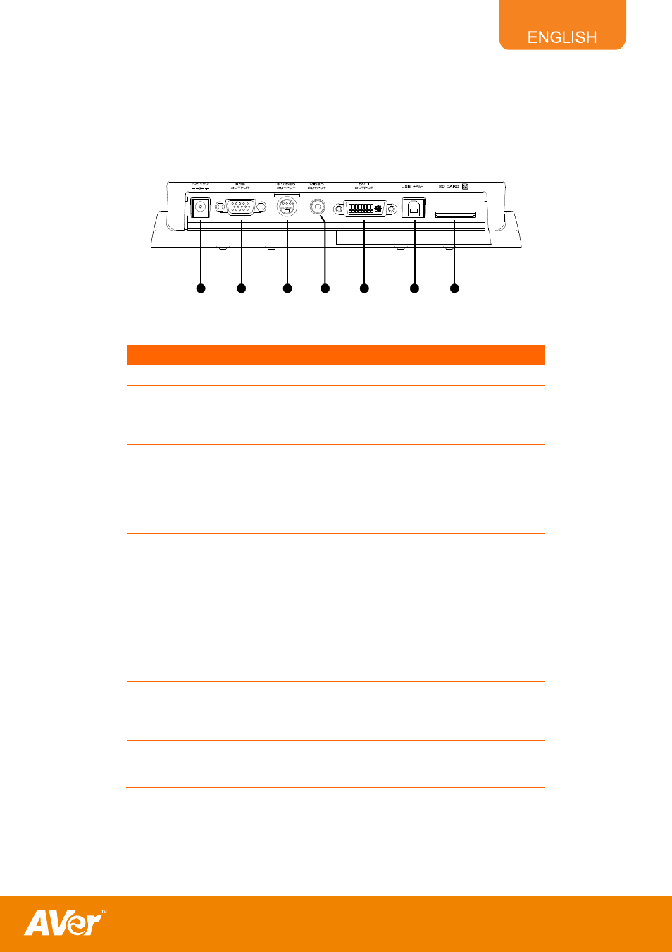
The ports at the rear and right panel of the SPC300+ enable you to connect the unit to a computer, graphics
display monitor, LCD/DLP projector, TV or other devices. Illustrated below are the ports located at the rear and
right panel of the SPC300+ with their corresponding labels.
Rear Panel
(1) (2)
(6) (7)
(5)
(4)
(3)
Name
Function
(1) DC 12V port
: Connect the power adapter into this port.
(2) RGB output port
: Output RGB signal from camera, RGB input port,
or the captured images from the memory source
and preview it on a VGA/Mac monitor or LCD/DLP
projector.
(3) S-Video output port
: Output the signal from the camera or the captured
images from the memory source on TV or AV
equipment.
Connecting the S-Video/RS-232 cable allows
using a computer to control SPC300+ thru RS-232
connection.
(4) Video output port
(RCA/Composite)
:
Output the signal from the camera or the captured
images from the memory source on TV or AV
equipment.
(5) DVI-I output port
: Output RGB signal from camera, RGB input port,
or the captured images from the memory source
and preview it on a LCD/Mac monitor or LCD/DLP
projector with DVI-I interface.
If the display device does not support DVI-I, it can
only display RGB signal from camera and preview
captured images.
(6) USB port
: Use SPC300+ as a USB Camera or Mass Storage
device allowing you to transfer the captured
images to and from the SPC300+ memory source
and PC.
(7) SD card slot
: Insert the SD card with the label facing up. This
supports 16~512MB card capacity and only
accepts FAT16 formatted card.