1a 1b – Alumax L-522 User Manual
Page 14
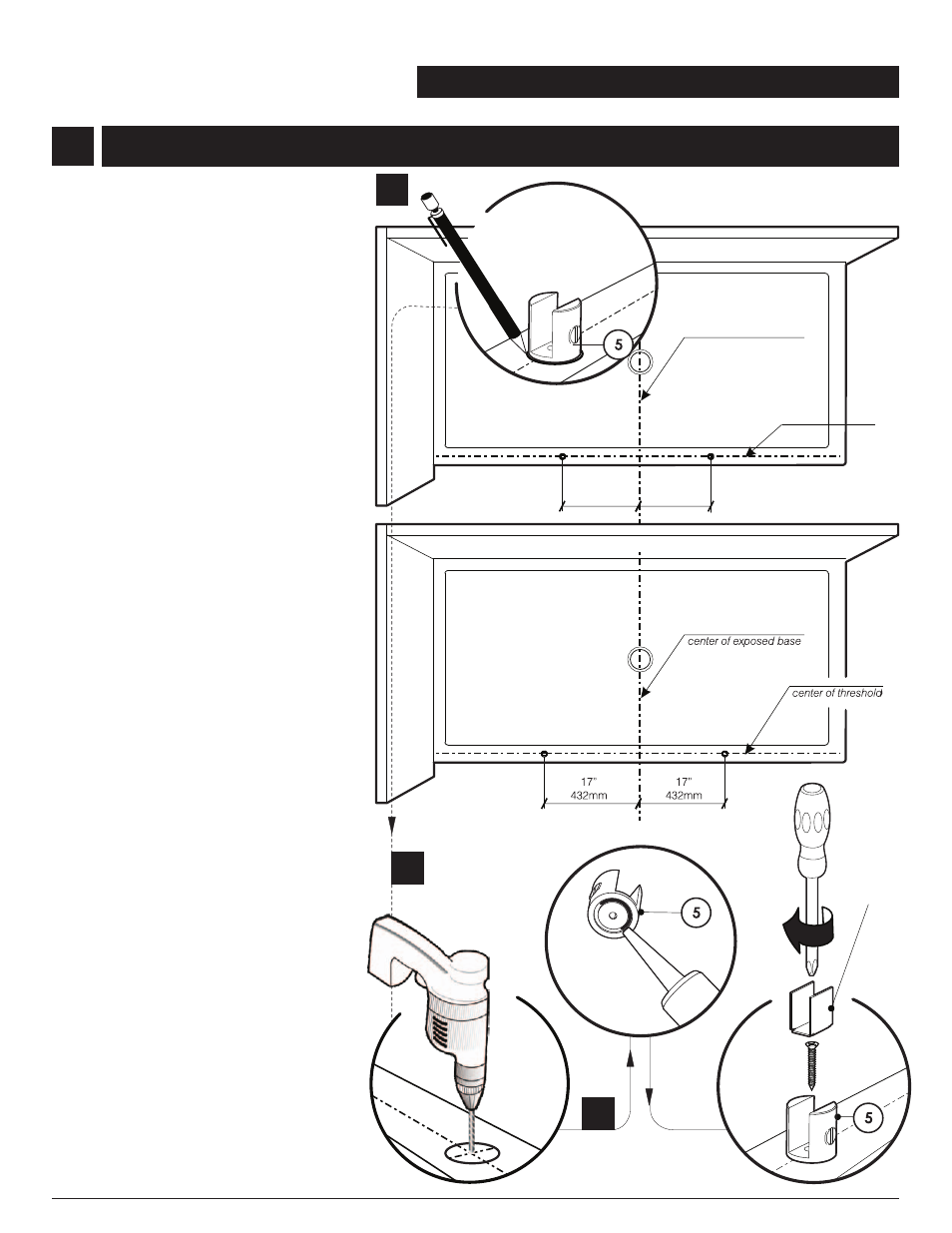
BOTTOM CLIPS INSTALLATION
500X, 501X, 502X, 511X, 512X, 521X, 522X, 521TBX, 522TBX
1a. Using the measuring tape, mark the center
of the threshold of the base. Find the center
of the exposed base and draw a line to the
center of the threshold. The line must be
perpendicular . Place both bottom clips (5)
along the line of the center of threshold.
Mark the screw location following the
dimensions shown in the drawing. For
model 6305 - 6306 - 6307 - 6308
use
drawing A. For model 6309 use drawing
B. Dimensions on the drawing are for
ABN3672 base installation. For model
V6309 use drawing B.
1b.
1c. Apply
Remove the bottom clips to drill the base
using #1/8” drill bit.
silicone into the groove at the bottom
of the clip and around the hole dirlled.
Fasten the bottom clips to the base using
the provided screws. Place the gaskets into
bottom clips slots.
1
1a
1b
13.25”
335mm
13.25”
335mm
center of threshold
center of exposed base
5
1c
11
501X, 502X, 511X, 512X, 521X, 522X, 521TBX, 522TBX
500X
DRAWING A
DRAWING B
INSTRUCTION MANUAL
CLEAR GASKET
5