Craftsman 113.244513 User Manual
Page 9
Attention! The text in this document has been recognized automatically. To view the original document, you can use the "Original mode".
5.
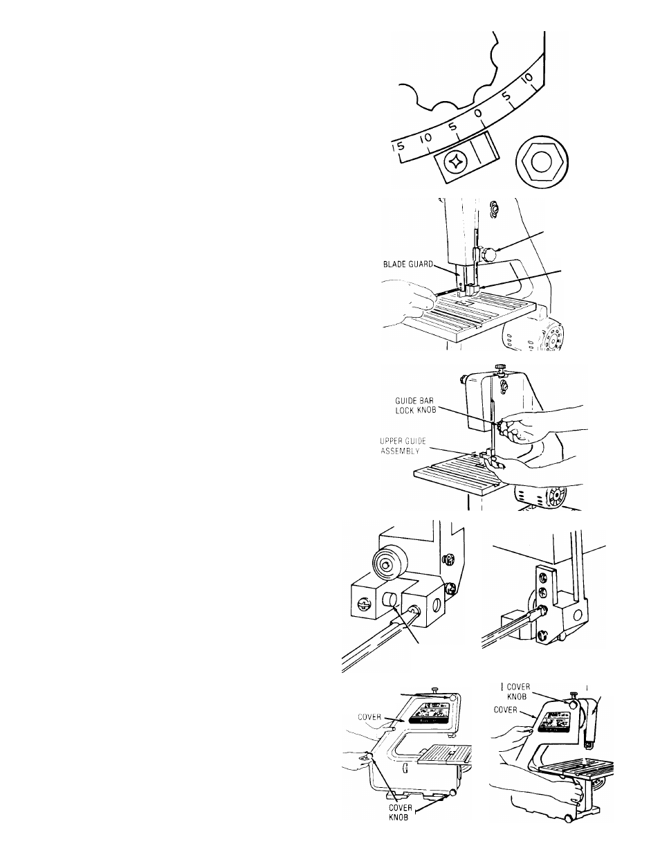
Locate bevel indicator and 10-24x1/4 pan
cross hd. screw in loose parts bag.
6. Install bevel indicator and screw as shown
using a Phillips screwdriver.
NOTE:
This unit comes with the Band Saw blade
installed,
assembly
continues
on
p.
10,
“Tension
ing the Blade.”
REPLACING THE BLADE
1.
Loosen
the
guide
bar
lock
knob
and
position
the
upper
guide
assembly
approximately
one
inch above the table and tighten lock knob.
2.
Loosen
the
two
blade
guard
mounting
screws
and remove the blade guard.
GUIDE BAR
LOCK KNOB
UPPER GUIDE
ASSEMBLY
3.
Loosen
the
guide
bar
lock
knob
and
position
the
upper
guide
assembly
approximately
two
inches above the table as shown and tighten
the lock knob.
4.
Remove
table
insert,
truss
head
screw,
wash
er
and
wing
nut
from
the
table
(See
Assem
bly,
p.
13
-
"Adjusting
the
Table”).
Replace
these
parts
after
the
blade
is
installed,
ten
sioned and tracked.
5.
Loosen
the
two
screws
in
the
front
of
the
upper
blade
guide
assembly
that
secure
the
blade guides and separate them about 1/8".
6.
Loosen
the
two
screws
in
the
side
of
the
upper
guide
assembly
and
slide
guides
and
thrust bearing all of the way back.
7.
Tighten all screws.
BLADE
GUIDE
COVER
KNOBS
Loosen
the
three
(3)
cover
knobs
by
turning
counterclockwise and remove cover.
NOTE:
Replace
the
bandsaw
cover
after
blade
is
properly installed, tensioned and tracked.
FRAME