Step, Installation step, Steps – Craftsman 139.53403 User Manual
Page 14
Attention! The text in this document has been recognized automatically. To view the original document, you can use the "Original mode".
Installation
STEP?
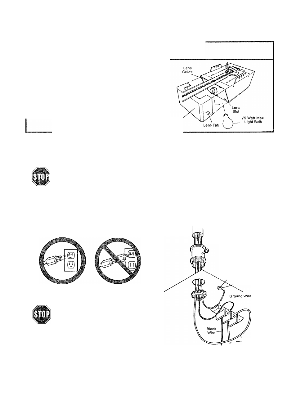
Install Light and Lens
PROCEDURE: Install a light bulb.-(75 Watts Max
imum) in socket as shown The light will turn on and
remain lit for 4-1/2 minutes when power is connected.
After 4-1/2 minutes it will turn off..
If light bulb burns out prematurely due to vibra
tion, replace with a “rough service” bulb.
INSTALLING LENS:
Slide lens into the lens guides as shown. Snap bottom
tabs into lens slots
Light Lens
STEPS
Connect Electric Power
TO AVOID SERIOUS PERSONAL INJURY FROM ENTANGLEMENT, REMOVE ALL ROPES
CONNECTED TO THE GARAGE DOOR BEFORE OPERATING OPENER.
TO AVOID DAMAGE TO GARAGE DOOR AND OPENER, MAKE DOOR LOCKS INOPERATIVE
BEFORE CONNECTING ELECTRIC POWER. USE A WOOD SCREW OR NAIL TO HOLD THE
LOCKS IN “OPEN” (UNLOCKED) POSITION,
INSTALLATION AND WIRING MUST BE IN COMPLIANCE WITH LOCAL ELECTRICAL AND
BUILDING CODES,
OPERATION AT OTHER THAN 120V 60Hz WILL CAUSE OPENER MALFUNCTION AND DAMAGE.
Opener MUSTbe permanently wired or plugged into
a grounded 3-prong receptacle wired according to
local electrical codes DO NOT use a 2-wire adapter.
DO NOT use an extension cord
PERMANENT WIRING
CONNECTION
Ground Tab
Ground Screw
RIGHT
WRONG
IF LOCAL CODES REQUIRE PERMANENT WIRING:
DISCONNECT POWER AT FUSE BOX
BEFORE PROCEEDING..
PROCEDURE: Refer to illustration. Make connec
tion through the 7/8 inch diameter hole in top of
opener chassis
1. Remove opener chassis cover by removing the
cover screws
2 Remove attached 3-prong cord
3 Connect the black (line) wire to the black wire on
terminal block; white (neutral) wire to the white
terminal wire; the green (ground) wire to green
ground screw.
White Wire
CAUTION: BE SURE THAT UNIT IS GROUNDED
ACCORDING TO LOCAL CODE.
IMPORTANT NOTE: TO AVOID INSTALLATION
DIFFICULTIES, DO NOT RUN OPENER NOW.
14