A warning, Fig.r, Fig.s – Craftsman 137.218250 User Manual
Page 14: Blade tilt pointer, Blade parallel to miter gauge groove (fig.t,u), Initial adjustment (fig.t), 45° stop
Attention! The text in this document has been recognized automatically. To view the original document, you can use the "Original mode".
A WARNING
To avoid injury from an accidental start, make sure the
switch is in the OFF position and the plug is not
connected to the power source outlet.
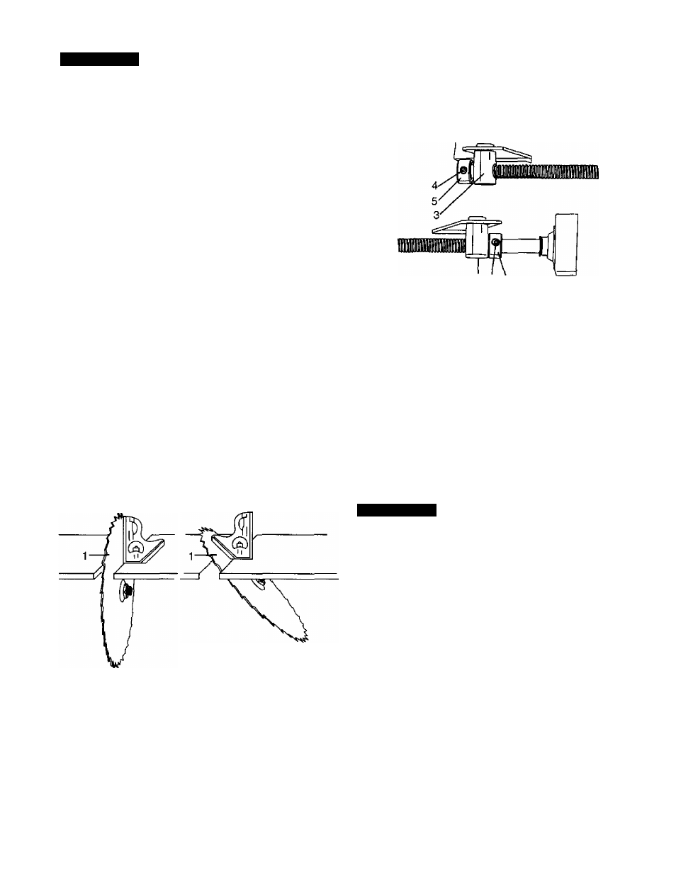
ADJUSTING THE 90° AND 45° POSITIVE STOPS
(FIG. R, S)
Your saw has positive stops that will quickly position the
saw blade at 90° or 45° to the table. These stops were
set at the factory. Make adjustments only if necessary.
90
1
.
2
.
3.
4.
6
.
7.
° Stop
Disconnect the saw from the power source.
Turn the blade elevation handwheel and raise the
blade to the maximum elevation.
Loosen the blade bevel lock knob and move the
blade to the maximum vertical position. Tighten the
lock knob.
Place a combination square on the table and
against the blade (T) to determine if the blade
is 90° to the table. (FIG. R)
If the blade is not 90° to the table, loosen the two
set screws (4), located in the bottom of the table saw,
(FIG. S) with the 3mm hex key, and back off the
collar (5).
Loosen the bevel lock knob. Turn the blade tilting
handwheel to move the blade until it is 90° to the
table.
Adjust the collar (5) so it contacts the bracket (3)
when the blade is 90° to the table. Tighten the
two set screws (4),
Fig.R
90'
45'
4.
Loosen the bevel lock knob; turn the tilting
handwheel to move the blade until it is 45° to the
table,
5. Adjust the collar (5) so it contacts the bracket (3)
when the blade is 45°, Tighten set screws (4).
Fig.S
3 4 5
BLADE TILT POINTER
1. When the blade is positioned at 90°, adjust the
blade tilt pointer to read 0° on the scale.
2.
Loosen the holding screw, position the pointer over
0° and tighten the screw.
NOTE:
Make a trial cut on scrap wood prior to making
critical cuts. Measure for exactness.
BLADE PARALLEL TO MITER GAUGE
GROOVE (FIG.T,U)
This adjustment was made at the factory, but it should
be rechecked and adjusted if necessary.
A WARNING
To prevent personal injury:
•
Always disconnect plug from the power source when
making any adjustments.
•
This adjustment must be correct or kickback could
result and accurate cuts cannot be made.
Initial adjustment (FIG.T)
45° Stop
1. With the blade in the upright 90° position, loosen the
bevel lock knob. Turn the blade tilting handwheel and
move the blade to the 45° position as far as it will go.
2. Place the combination square on the table as shown
in
(FIG. R)
to check if the blade is 45° to the table.
3. If the blade is not 45° to the table, loosen the two set
screws (4) located under the table saw (FIG. S) with
a 3 mm hex key, and back off the collar (5).
1
.
2
.
3.
4.
5.
6
.
7.
Remove the yellow switch key and unplug
the saw.
Move the blade guard out of the way.
Raise the blade to the highest position and set at
the 0° angle {90° straight up).
Select and mark, with a felt tip marker, a blade
tooth having a “right set”.
Place the combination square base (1) into the
right side miter gauge groove (2). (FIG.T)
Adjust the rule so it touches the front marked tooth
and lock the ruler so it holds its position in the
square assembly.
Rotate the blade bringing the marked tooth to the
rear and about 1/2 inch above the table.
14