Blade guard assembly (fig. k, l, m), Fig. k, Fig. l – Craftsman 137.218250 User Manual
Page 12: Adjustment instructions, A warning, Adjusting the table extension (fig. o), Safety instructions
Attention! The text in this document has been recognized automatically. To view the original document, you can use the "Original mode".
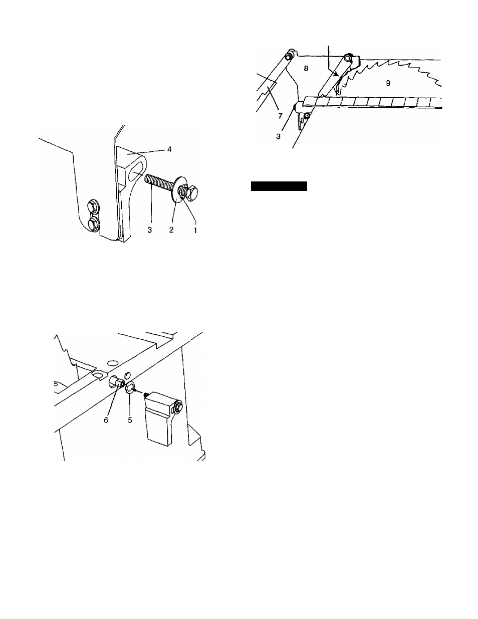
BLADE GUARD ASSEMBLY (FIG. K, L, M)
1. Set the blade to maximum height and the tiit to zero
degrees on the bevel scale with the hand wheels.
Lock the blade lock knob.
2.
Place the external toothed lock washer (1) and a
steel flat washer (2) onto the long hex. head bolt (3).
Insert the bolt into the splitter bracket (4) as shown.
(FIG. K)
Fig. K
Fig. M
anti-kickback pawl
3.
4.
5.
6
.
7.
8
.
Place the oval washer (5) on the pivot rod (6).
(FIG. L)
Install the bracket assembly (4) into the rear of the
saw table. Thread the bolt (3) into the internally
threaded pivot rod.
NOTE:
The splitter is removed from the illustration
for clarity.
Fig. L
ADJUSTMENT INSTRUCTIONS
A WARNING
To avoid injury from an accidental start, make sure the
switch is in the OFF position and the plug is not
connected to the power source, before making any
adjustments.
ADJUSTING THE TABLE EXTENSION (FIG. O)
NOTE:
The table extension may be installed on the right
side of the table, as needed, to support long
workpieces.
Position the blade guard arm (7) to the rear of the
table.
(FIG. M)
Using a straightedge, check that the blade guard
splitter (8) is aligned with the saw blade (9),
If straightening adjustment is necessary, loosen the
bolt (3) and shift the splitter assembly to the right or
left, or rotate.
When the splitter is properly aligned with the saw
blade, tighten the bolt.
NOTE:
The splitter must always be correctly aligned
so the cut workpiece will pass on either side without
binding or twisting to the side.
12