Ro replace motion drive belt (see fig. 26), Transmission removaureplacement, To adjust steering wheel alignment – Craftsman 944.602951 User Manual
Page 21: Front wheel toe-in/camber, Service and adjustments
Attention! The text in this document has been recognized automatically. To view the original document, you can use the "Original mode".
SERVICE AND ADJUSTMENTS
Depress cl utch/brake pedal and engage parking brake.
Meгlsure distance between brake operating arm and nut
“A" on brake rod.
If distance is otherthan f-9/16", loosen jam nut and turn
nut “A” until distance becomes 1 -9/16“. Retighten jam
nut against nut “A”.
Road test tractorfor proper stopping distance as stated
above. Readjust if necessary. If stopping distance is
still greater than six (6) feet in highest gear, further
maintenance is necessary. Contact your nearest au
thorized service center/department.
WITH PARKING BRAKE “ENGAGED”
NUT “A”
JAM NUT
PERATING
ARM
DO NOT TOUCH THIS NUT. IF FURTHER BRAKE ADJUST
MENT IS NECESSARY CONTACT YOUR NEAREST
AUTHORIZED SERVICE CENTER/DEPARTMENT
FIG. 25
ro
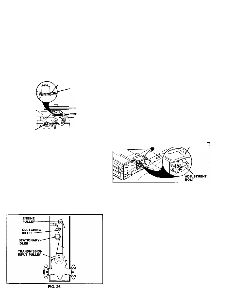
REPLACE MOTION DRIVE BELT
(See Fig. 26)
Parkthetractoron level surface. Engage parking brake. For
assistance, there is a belt installation guide decal on bottom
side of left footrest.
•
Remove mower (See TO REMOVE MOWER” in this
section of this manual.)
•
Remove belt from stationary idler and clutching idler.
' Pull belt slack toward rear of tractor. Carefully remove
belt upwards from transmission input pulley and over
cooling fan blades.
’ Pull belt toward front of tractor and remove downward
from around engine pulley.
•
Install new belt by reversing above procedure.
TRANSAXLE
MOTION
CONTROL
LEVER
NEUTRAL ADJUSTMENT (See Fig. 27)
The motion control lever has been preset at the factory and
adjustment should not be necessary.
•
Loosen adjustment bolt in front of the right rear wheel,
and lightly tighten.
• Start engine and move motion control lever until tractor
does not move fonward or backward.
•
Hold motion control lever in that position and turn engine
off.
•
While holding motion control lever in place, loosen the
adjustment bolt.
•
Move motion control lever to the neutral (N) (lock gate)
position.
•
Tighten adjustment bolt secu rely.
NOTE: If additional clearance is needed to getto adjustment
bolt, move mower deck height to the lowest position.
After above adjustment is made, if the tractor still creeps
fon/vard or backward while motion control lever is in neutral
position, follow these steps:
•
Loosen the adj ustment bolt.
•
Move the motion control lever 1/4 to 1/2 inch in the
direction it is trying to creep.
•
Tighten adjustment bolt securely.
•
Start engine and test.
•
If tractor still creeps, repeat above steps until satisfied.
MOTION CONTROL
LEVER
NEUTRAL
LOCK GATE
FIG. 27
TRANSMISSION REMOVAUREPLACEMENT
Should your transmission require removal for service or
replacement, it should be purged after reinstallation and
before operating the tractor. See “PURGE TRANSMIS
SION” in the Operation section of this manual.
TO ADJUST STEERING WHEEL ALIGNMENT
If steering wheel crossbars are not horizontal (left to right)
when wheels are positioned straight fonward, remove steer
ing wheel and reassemble per instructions in the Assembly
section of this manual.
FRONT WHEEL TOE-IN/CAMBER
The front wheel toe-in and camberare not adjustable on your
tractor. If damage has occu rred to affect the front wheel toe-
in or camber, contact your nearest authorized sen/ice
center/department.
21